


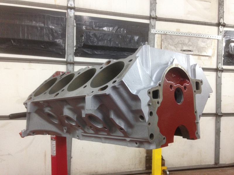
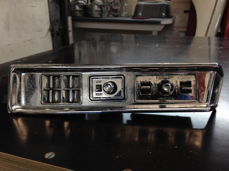
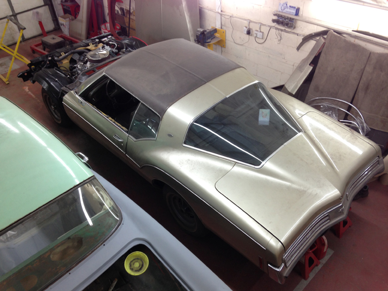
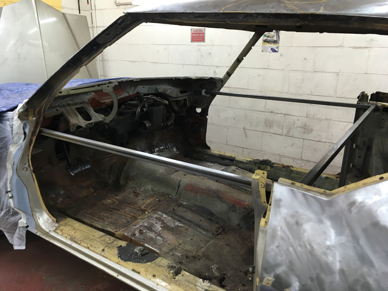
1973 Buick Riviera
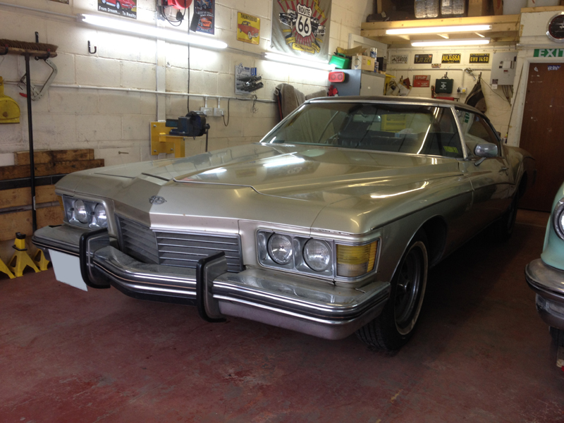
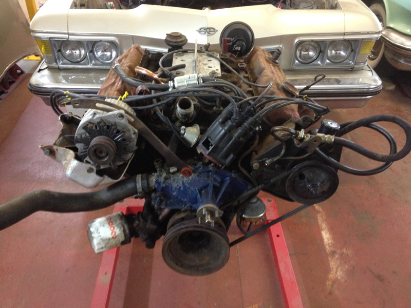
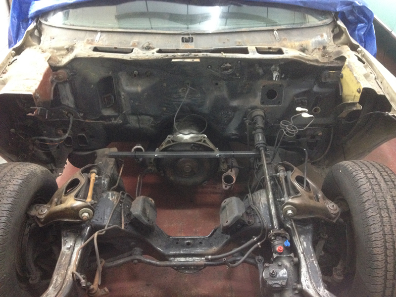
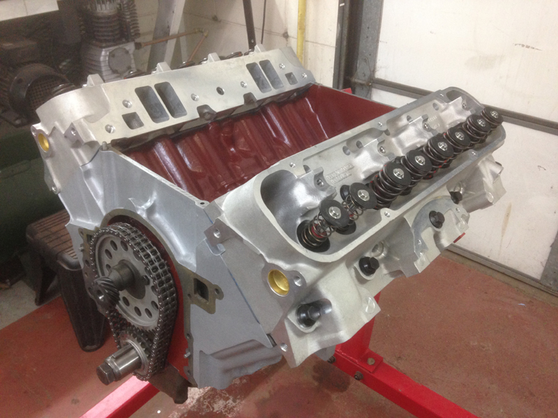
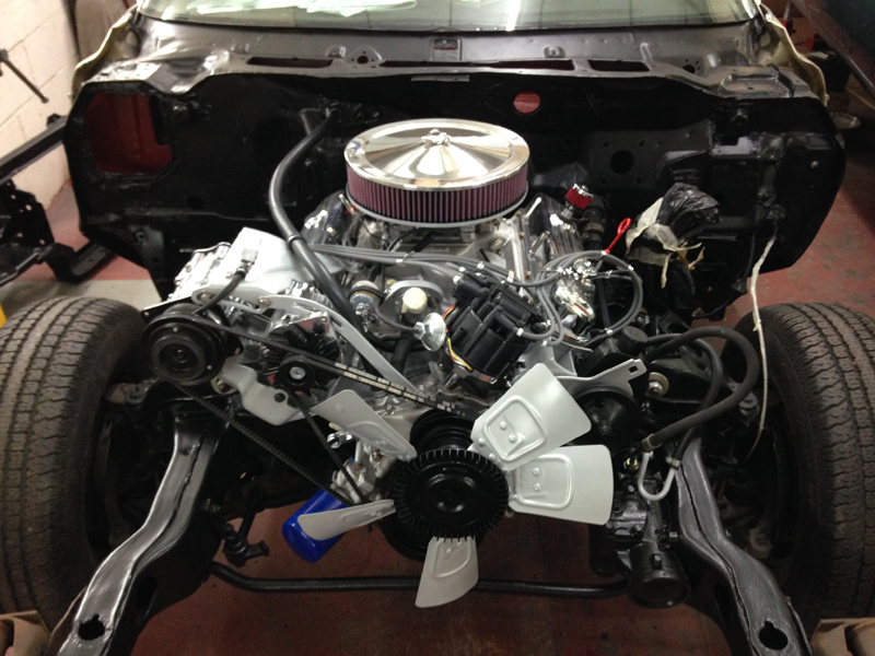
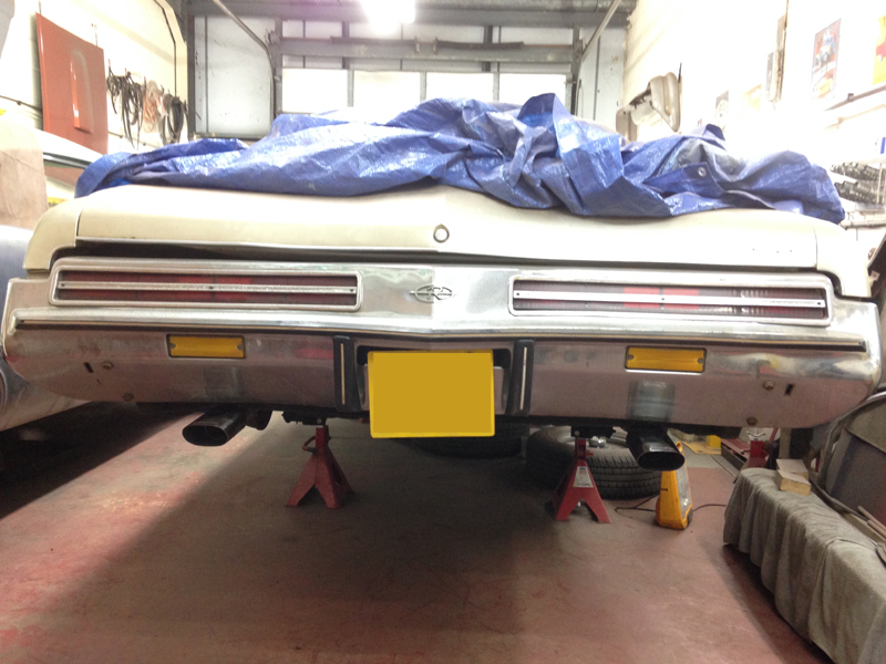
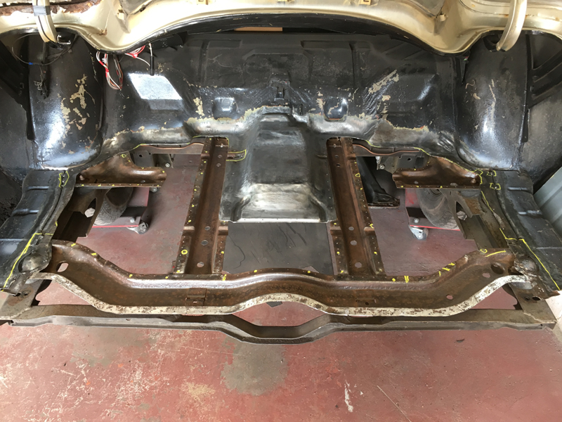
When the owner of this car contacted us and told us a bit about his car, we asked what were his plans for the car, the first words out of his mouth were "I want more power out of it." Straight away we knew this was a project that we wanted to get involved with. Our customer has owned this car for quite some time but unfortunatly it has been parked up since 1997 after developing a rough running problem. Now the time has come to give it a new lease of life and get it back on the road. Some of the plans for the car include, a complete rebuild of the original Buick 455 V8 with power upgrades using aluminium parts and uprated parts were possible, a complete new exhaust system, uprated front brakes and an engine bay tidy up are just some of the things that have been discussed so far.To start with are just a few photos of the car the day it arrived at our shop, from the front:
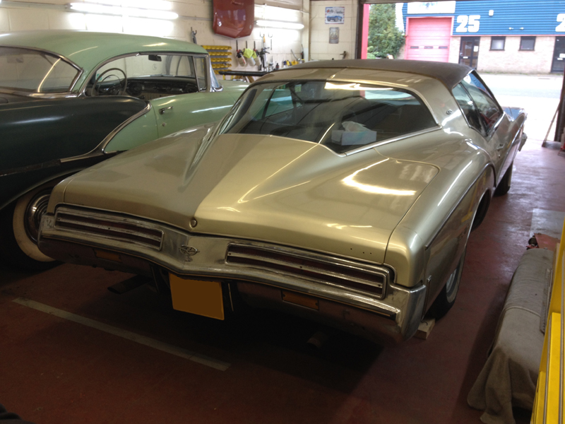
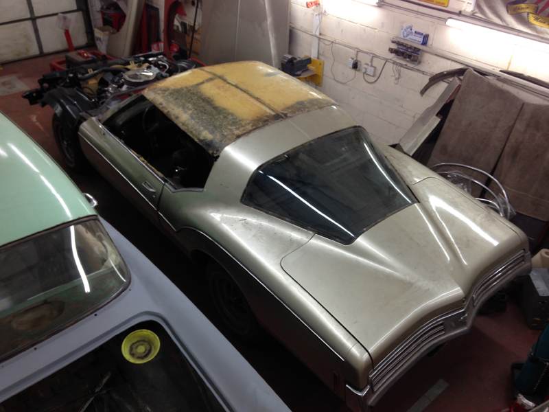
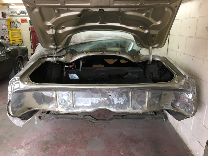
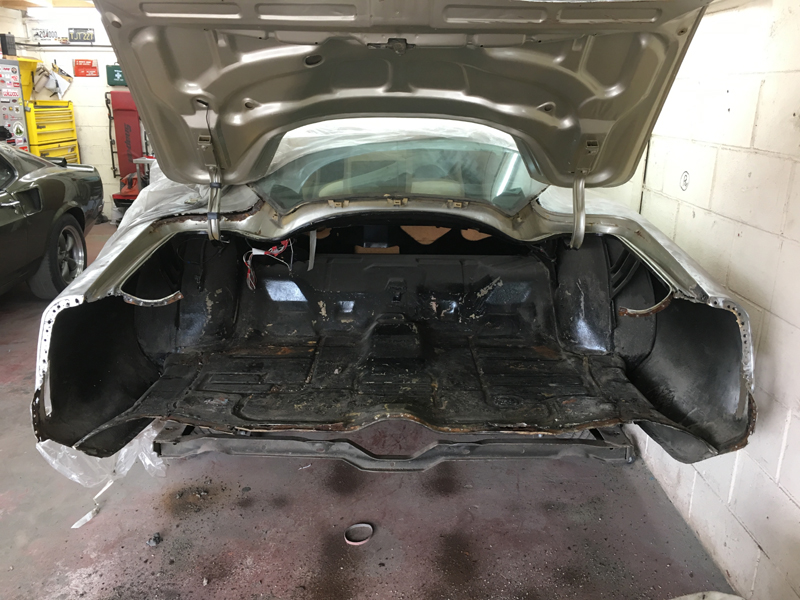
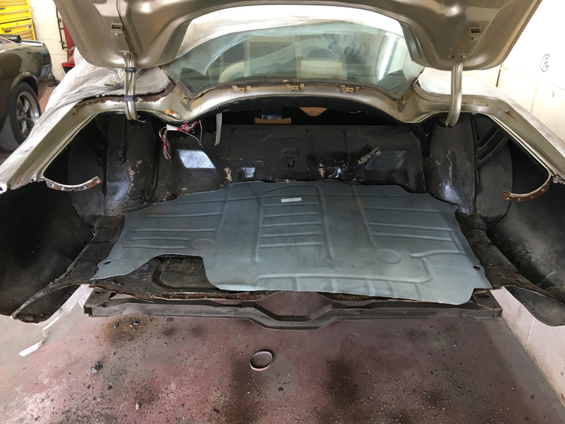
The rear:
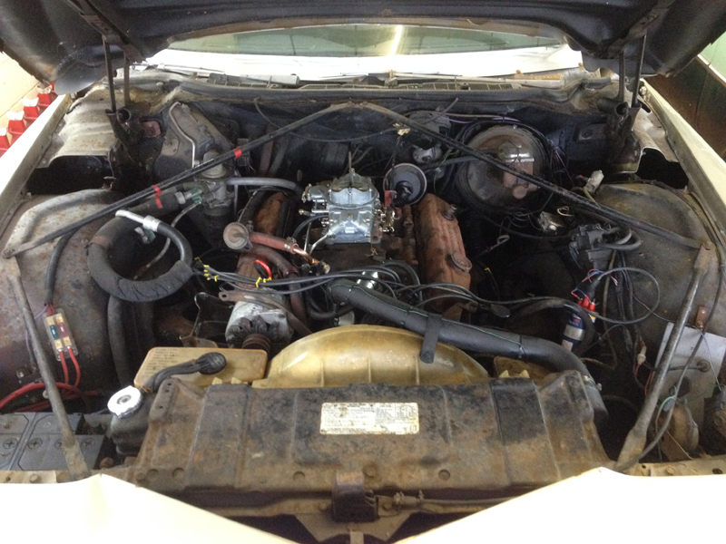
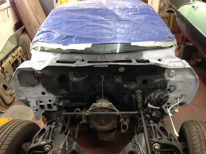
And under the bonnet:
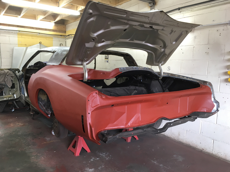
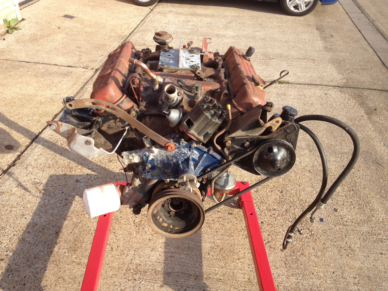
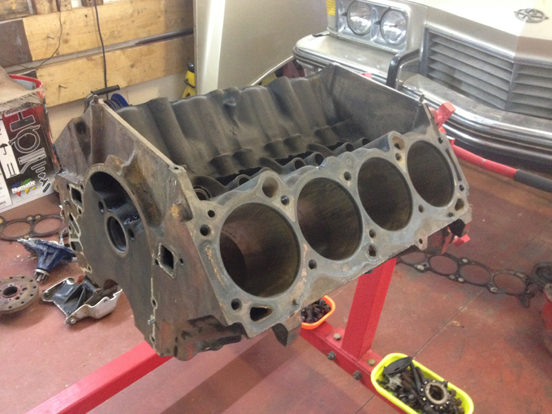
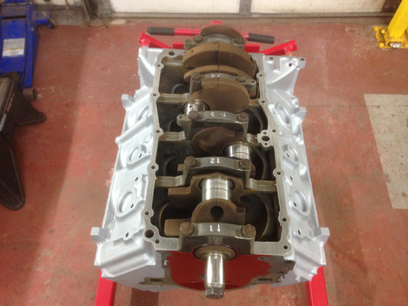
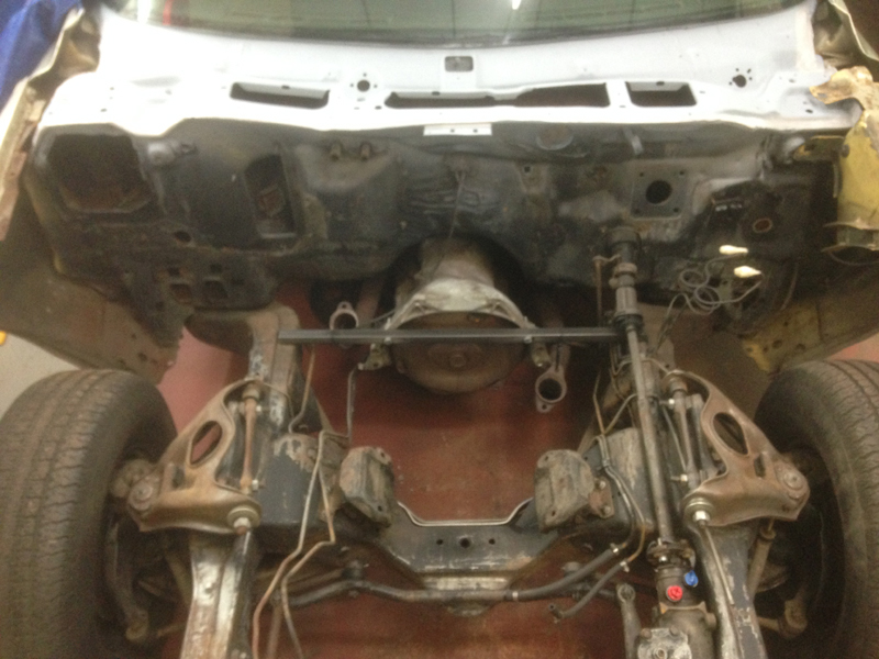
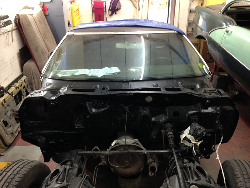
Where the car had been sat parked up for so long it was always going to need some work to get it back on the road, the owner of the car had managed to get the car to start after doing a few bits to the engine but it only ran for a few minutes, after shutting the engine off it wouldn't start again and had symptons of a blown head gasket leaking into combustion chambers. Since a full rebuild of the engine was allready on the cards, the first job was to pull the engine out the car:
Next after taking off a couple more parts from the engine was to give it a good clean up and de-grease before stripping it down so that we can find any more problems as we go:
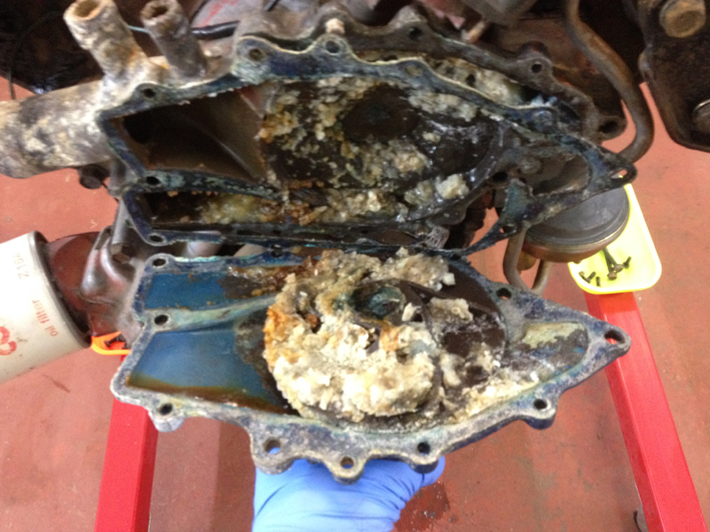
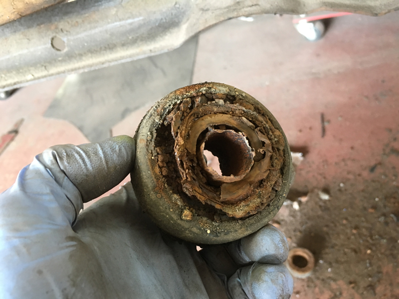
The first thing we found was a siezed water pump, after pulling the pump off the engine we quickly discovered why. The engines coolant hasn't had enough anti-freeze in it and over time the water has corroded away at the inside of the pump and engine block and also congealed into solid lumps:
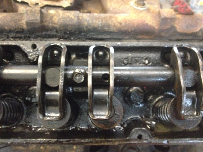
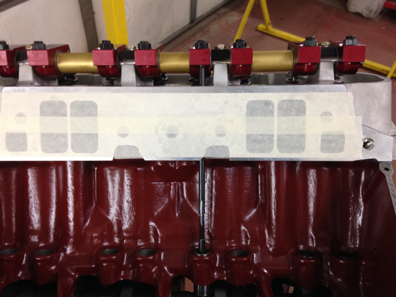
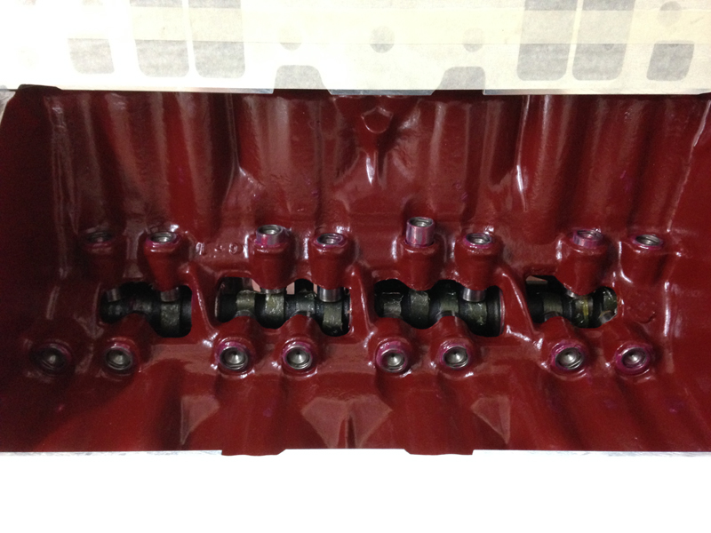
The next problem was on the passenger side cylinder head, one of the locating pins the holds the rocker arms over the valves in the correct place was laying in the cylinder head beside the valve and the rocker arm was sitting to one side over the valve. We don't know how long this problem had been like this but had the engine continued to be run like it then serious damaged could have occured:
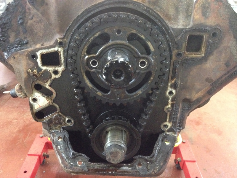
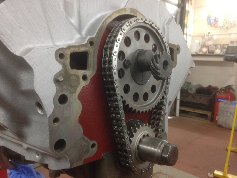
Up next is the timing chain, even though you can't see it much in the photo the chain is streched to a point were its no longer wise to keep using it, if the chain is streched at high engine RPMs the chain can jump its teeth and cause damage to the engine. Just a quick note, we had already taken the bolts out of the camshaft sprocket, they were in place before we took this picture:
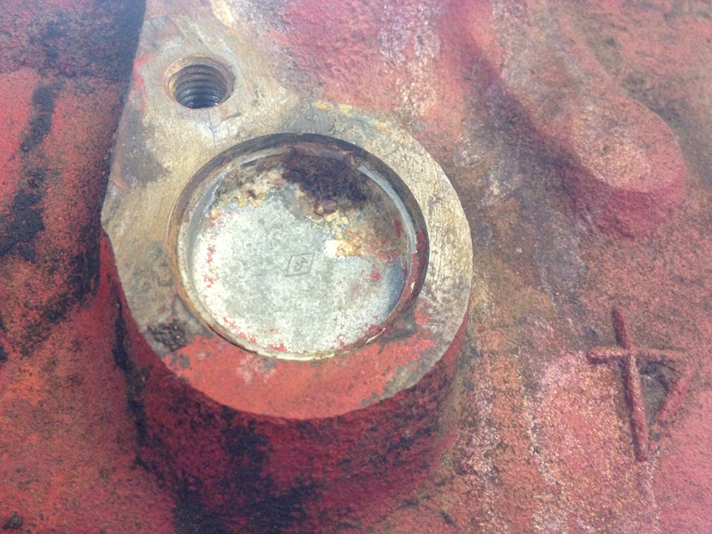
Next was one of the core plugs, there was a tiny pin hole in it caused by rust corrosion, had the engine not been checked out it would have had small water leak that would have only got worse over time:
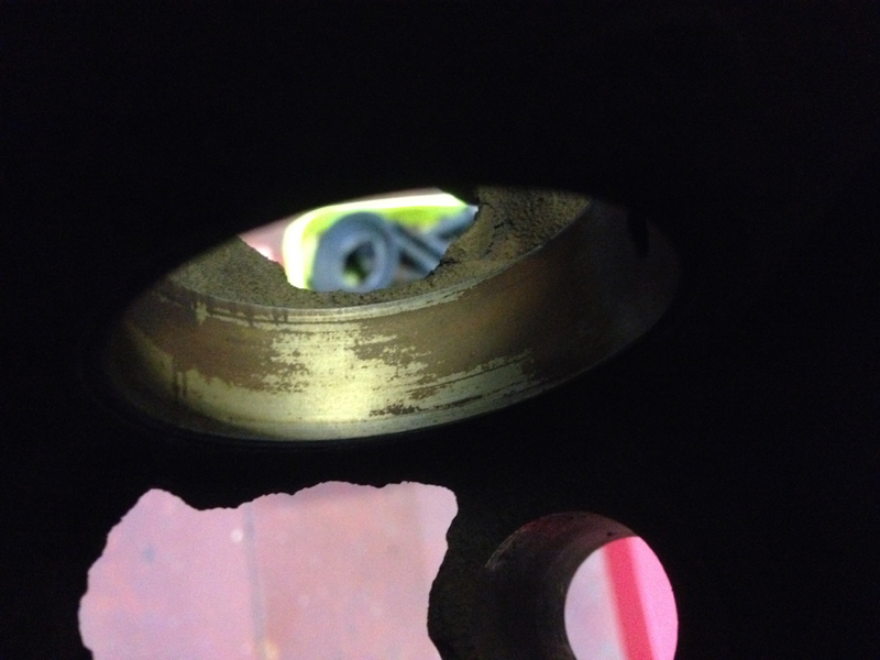
The next problem was found when we removed the camshaft, the protective hardened coating on the bearings that keeps the bearing smooth and from wearing the camshaft had started to wear away:
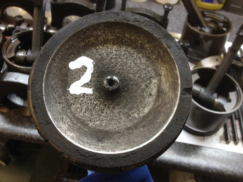
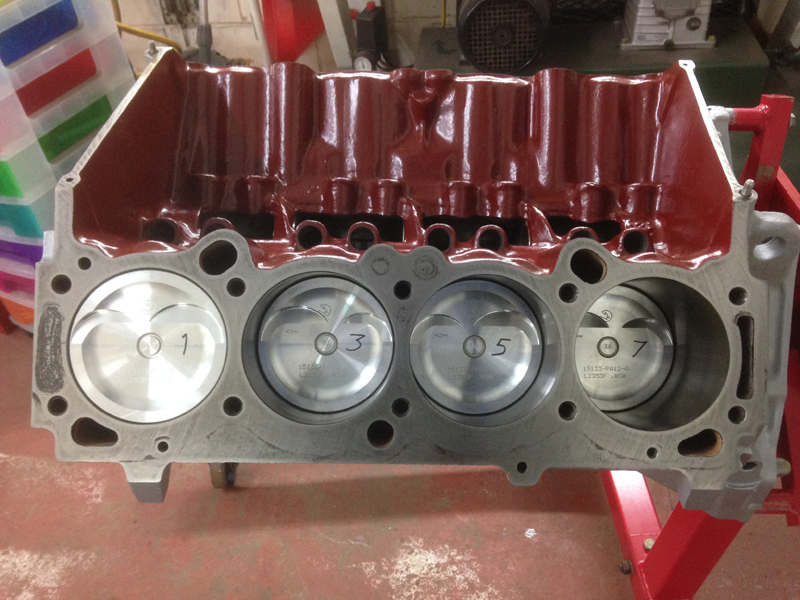
After pulling the cylinder heads and the pistons out the block we found that the cylinder head gasket on the passenger cylinder head had blown into cylinder number 2 and the piston has been sat in water for some time which had actualy started corroding away at the piston:
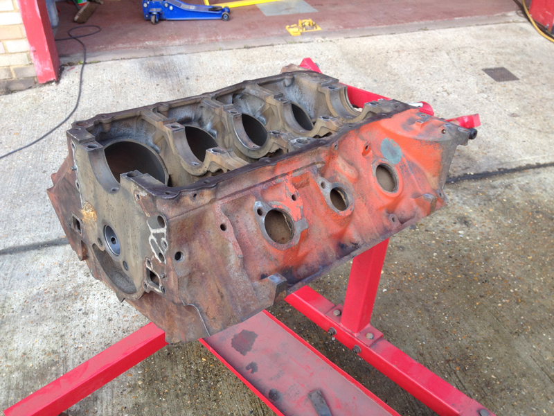
Once the engine was completly stripped we de-greased the block inside and out to check it over. The block is in good shape but the bores are worn past tollerence. The block will need a re-bore with new pistons and rings, the block will also be dipped in an acid tank to clean out the oil and passages and remove the rest of the dirt, gasket material and paint from the block:
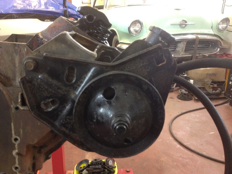
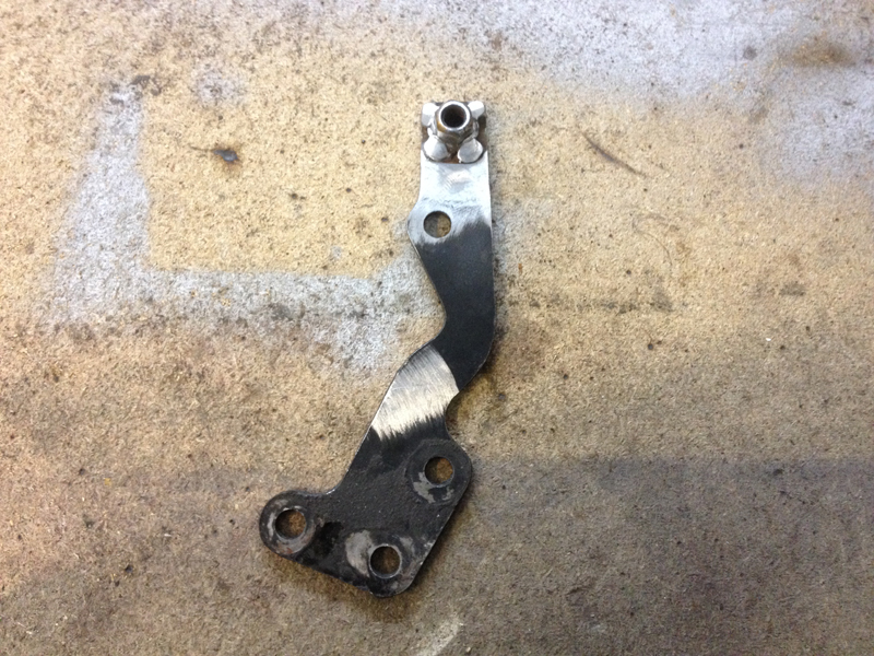
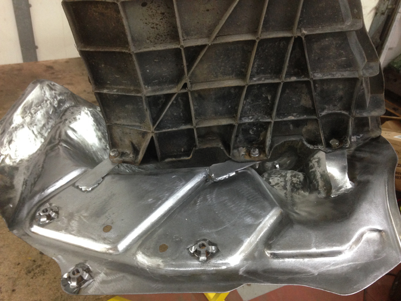
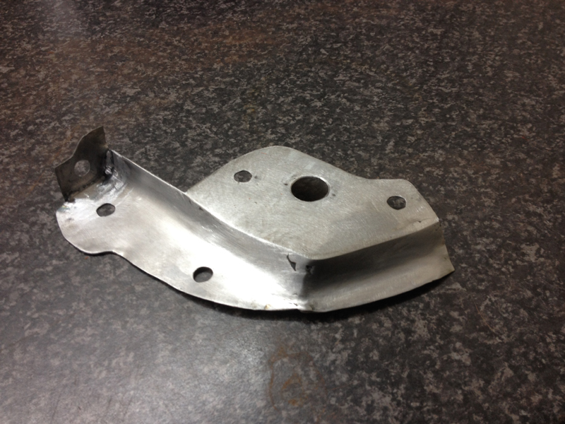
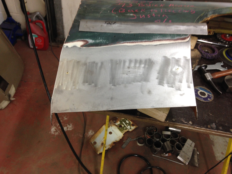
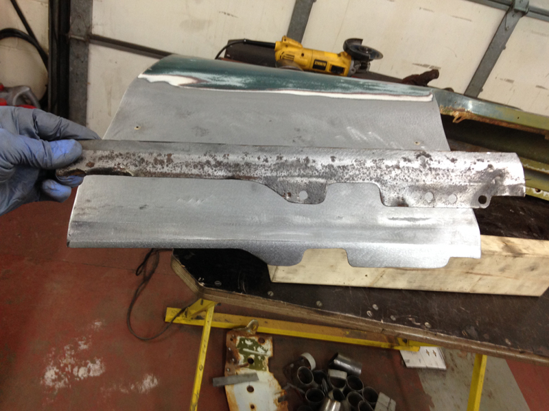
The stock power steering pump bracket is also the lower mounting point for the smog pump:
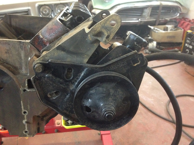
With the new engine set up we will no longer be using the smog set up, since we wont be needing the pump we decided to tidy up the bracket a little, we took off what we could from it without affecting the strength of the bracket itself:
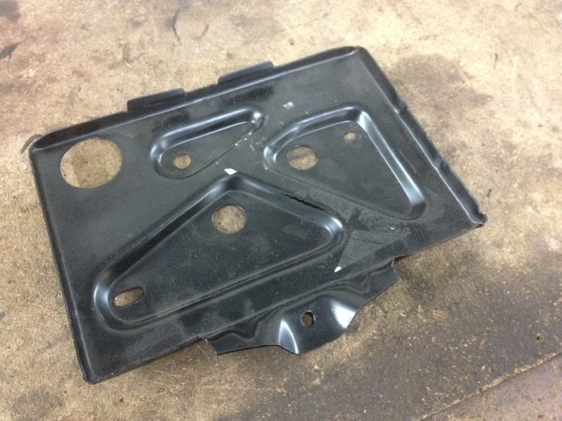
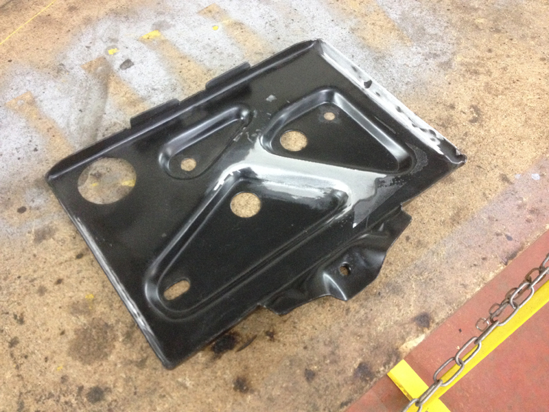
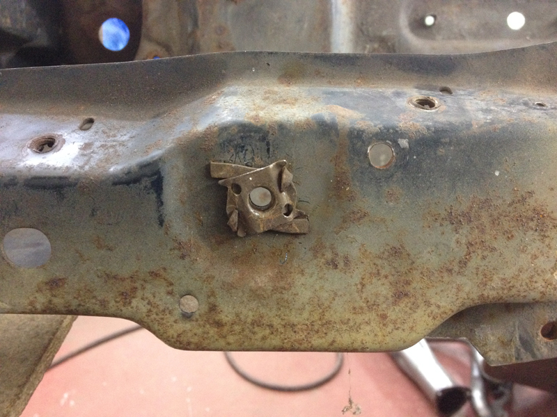
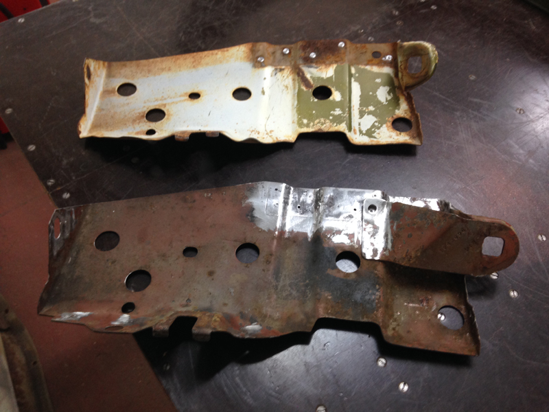
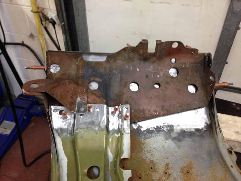
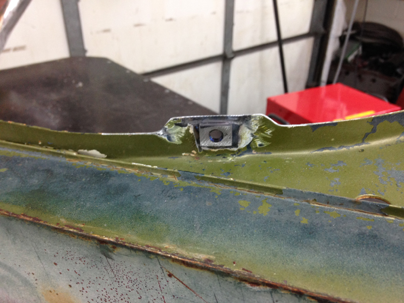
This next bracket is one of the air conditioning pump mounts, the very top hole should be a captive nut, at some point in time this has gone missing:
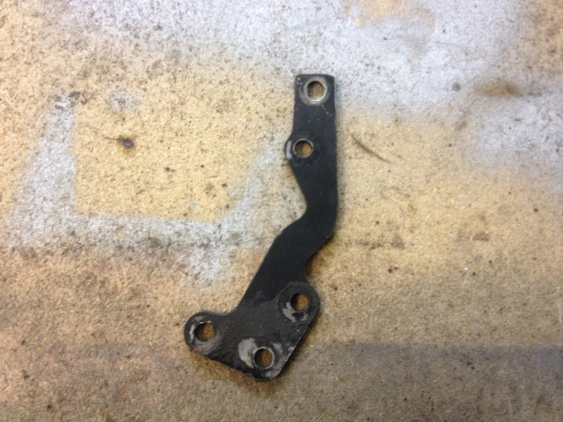
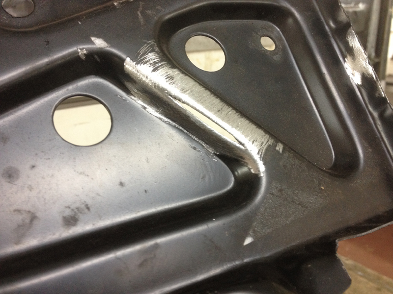
Before sending the brackets off to be powder coated we decided to weld on a new nut onto the bracket, the positioning of the nut on the rear of the bracket makes it very awkward to get a normal nut and spanner onto it, so this why the bracket should be put back to how it originaly was:
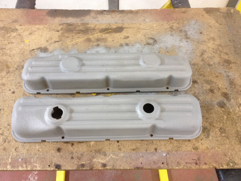
The owner of the car requested to have his original rocker covers chrome plated, they were painted and heavily rusted so we had them blasted first to inspect them:
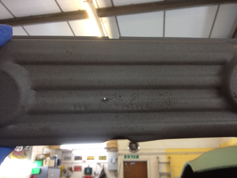
The passenger side cover had a tiny rust hole in it:
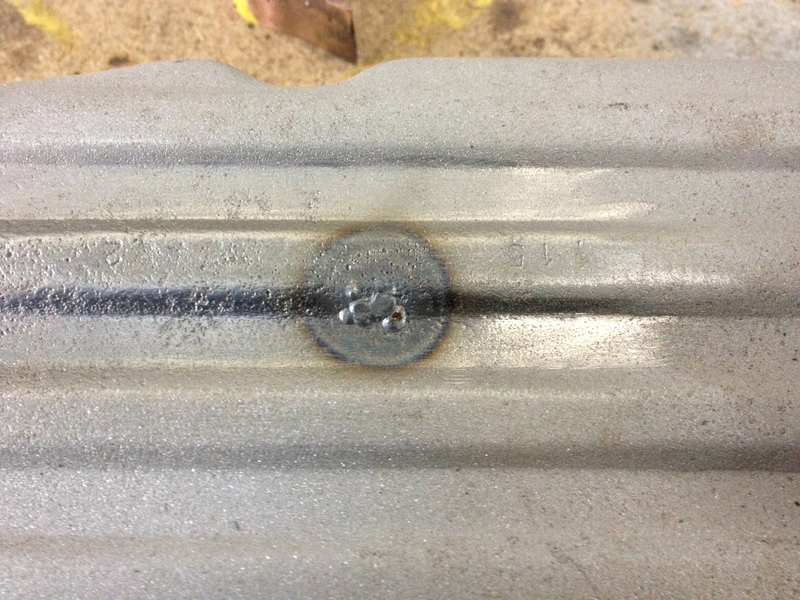
After some carefull welding the hole was gone:
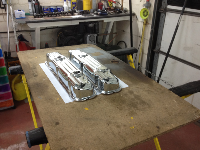
Then after some carefull grinding, we polished both covers to see how they would look and make sure the repaired area looked ok:
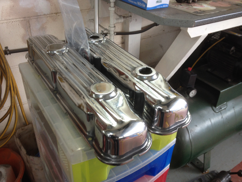
Then had both covers, the oil fill cap and the cover mounting tabs chrome plated:
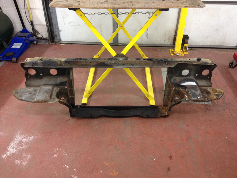
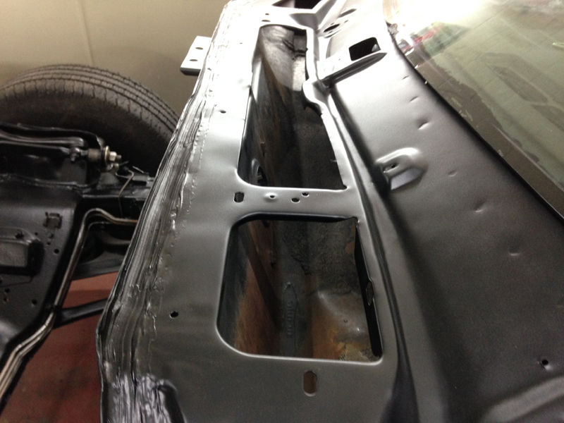
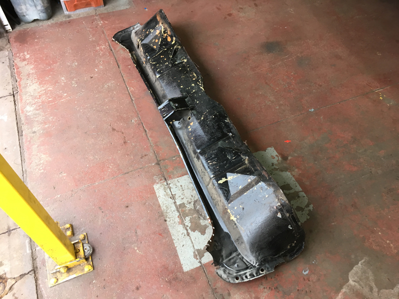
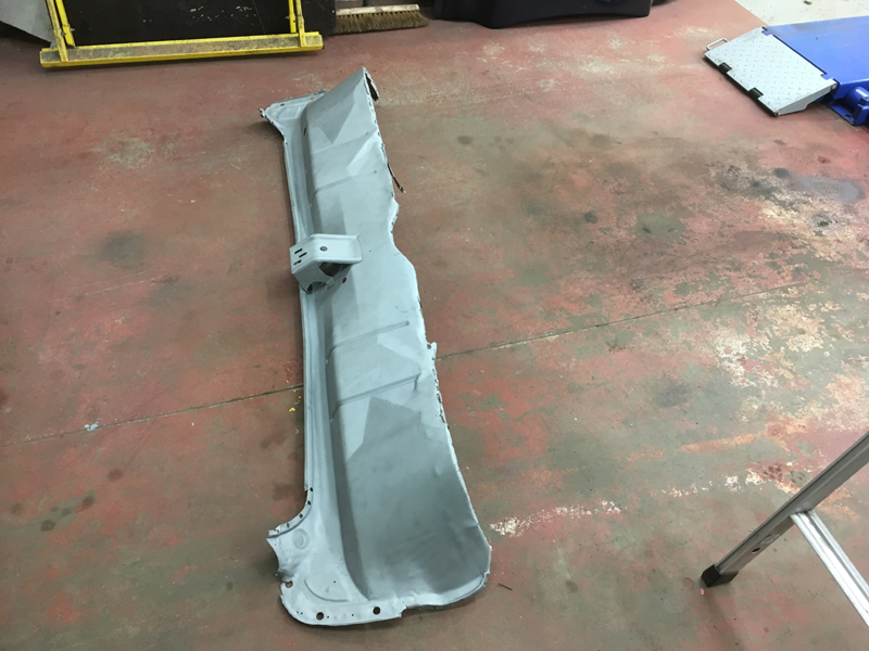
Next was to move onto the engine bay, the plan was to remove and repair the radiator core support and both inner wheel wells and have them powder coated and then re-paint the bulkhead. First up was the driver's inner wheel well. Overall this was in great shape, we had to straighten out a couple of small dents and weld up some no longer needed holes:
Just a quick before shot of 2 of the holes no longer needed:
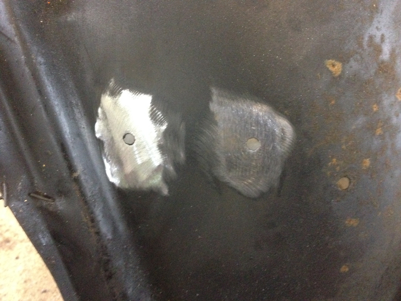
And then after:
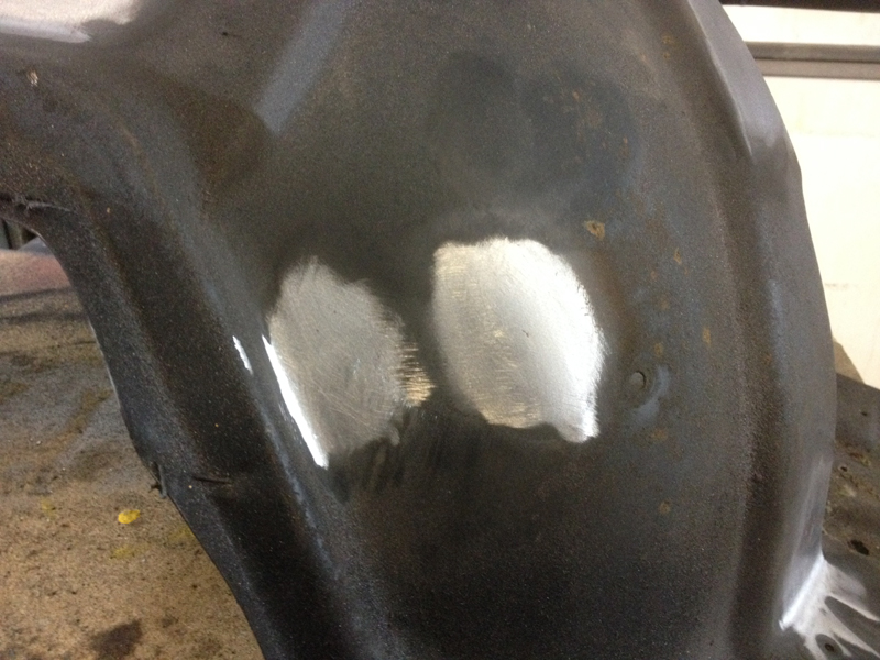
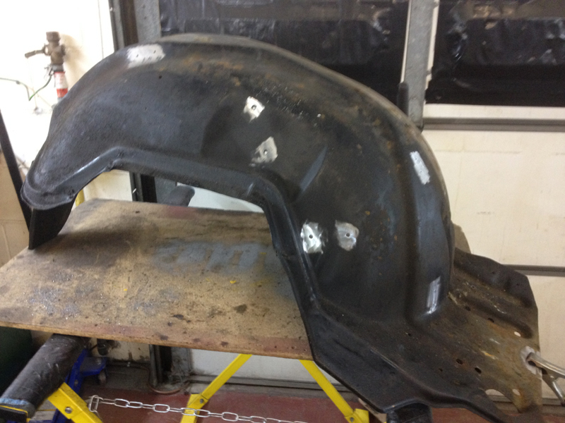
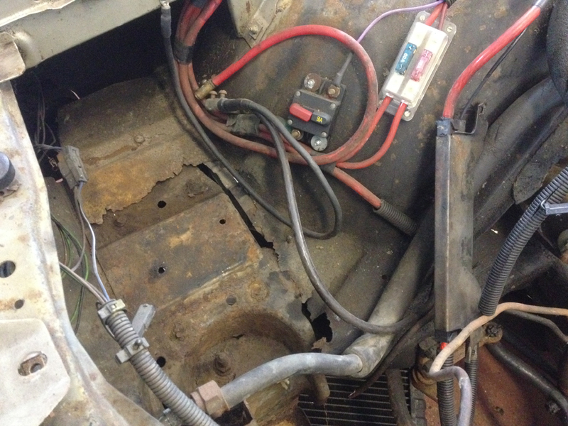
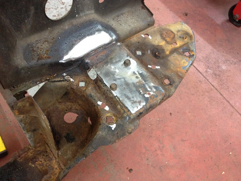
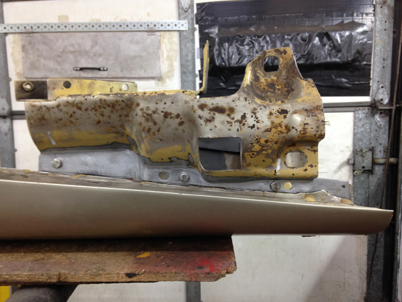
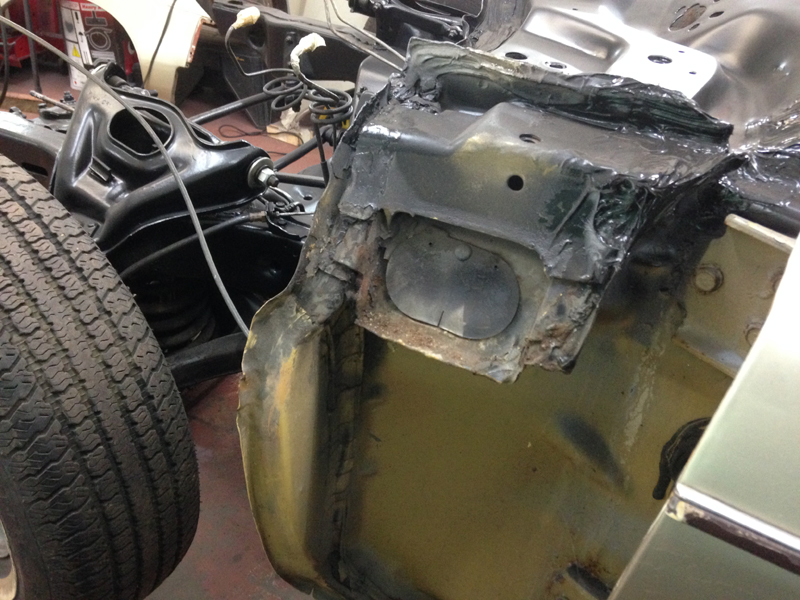
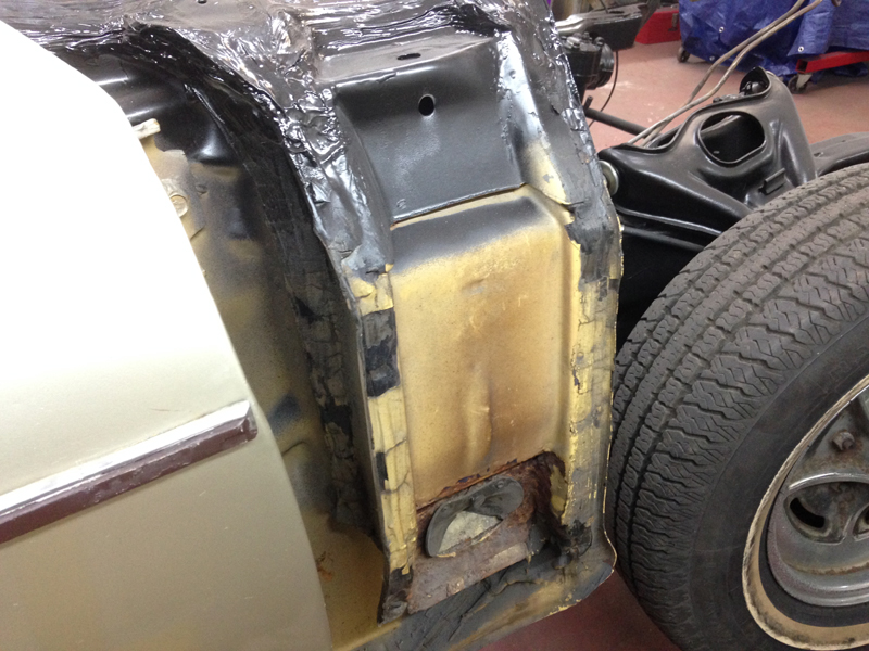
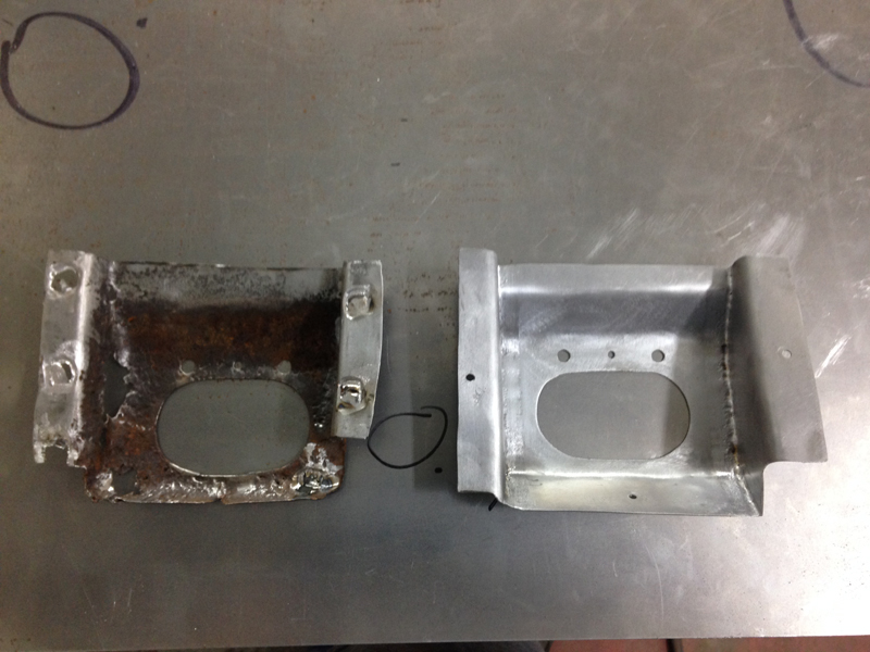
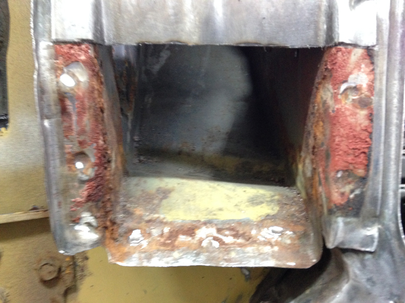
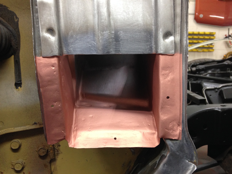
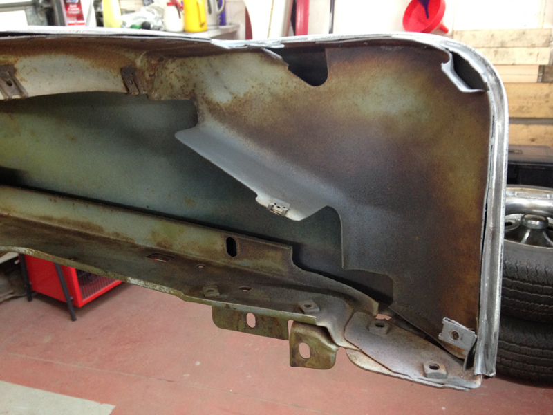
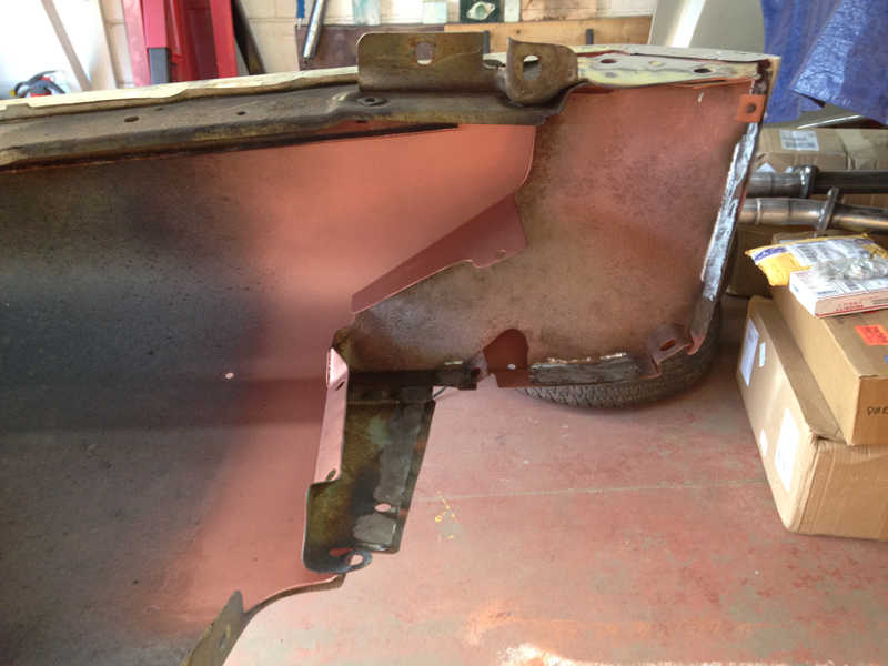
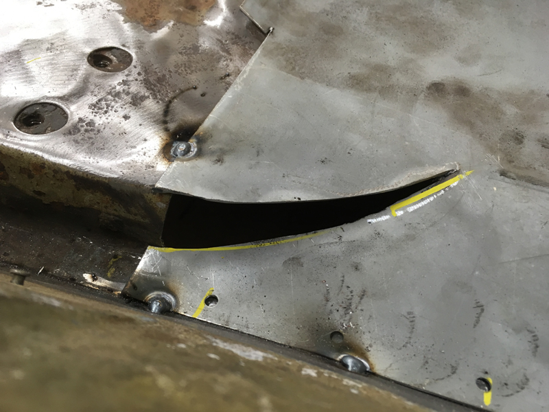
Unfortunatly the same could not be said for the passenger side inner wheel well. The battery tray was missing and sitting on a home made tray that wasnt mounted down properly nor was it capable of actualy clamping the battery in place and the area were the battery tray would sit had completly corroded away:
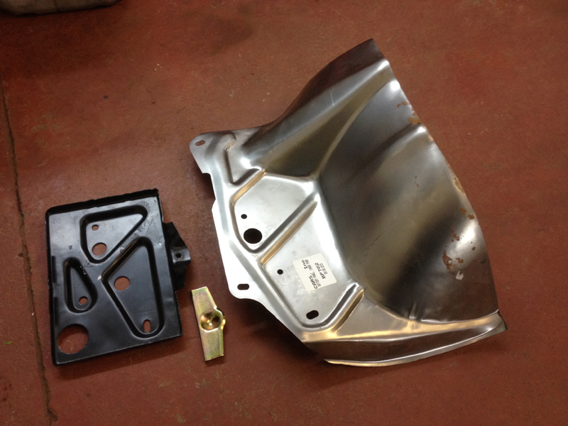
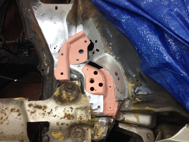
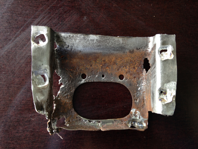
We spent some time searching online, it turns out a new item is not available and good used items just dont exist, even from dry state cars they are still like this due to years of battery acid eating away at the metal. A repair section is also not available. The option we came up with was to use a repair section for a Buick Skylark along with the matching battery tray and clamp and reshape it to fit:
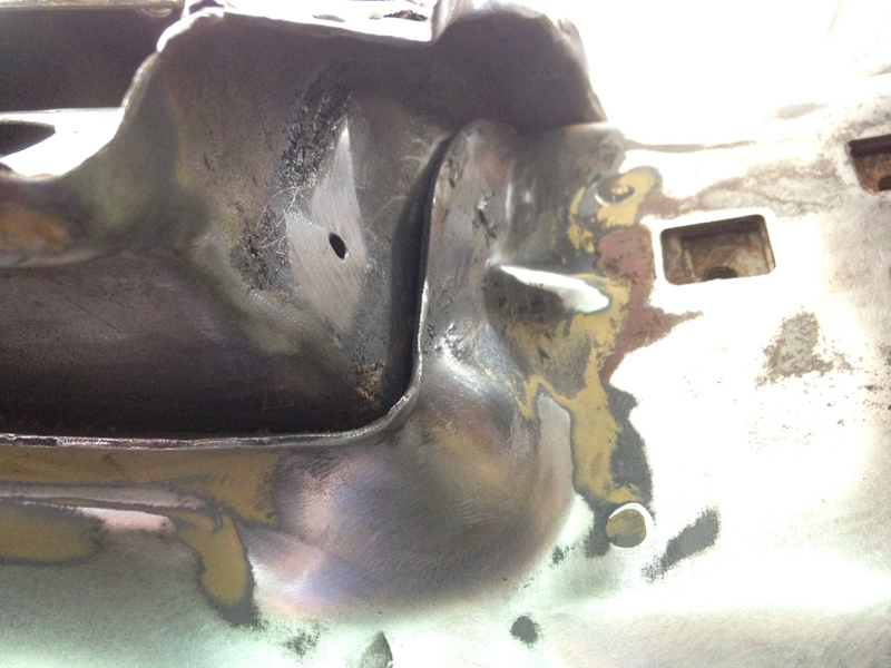
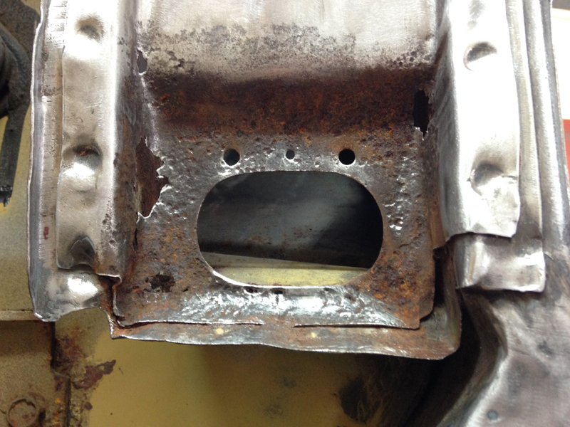
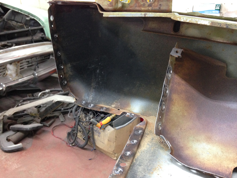
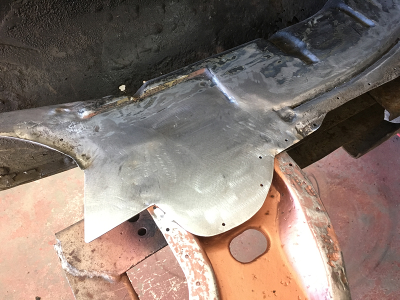
After the first attempt at offering the new section in the place it was clear this wasn't going to be a quick task. We ended up having to reshape the original panel as well as the new panel to get the 2 sections to even come close to one another:
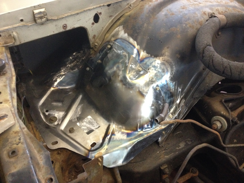
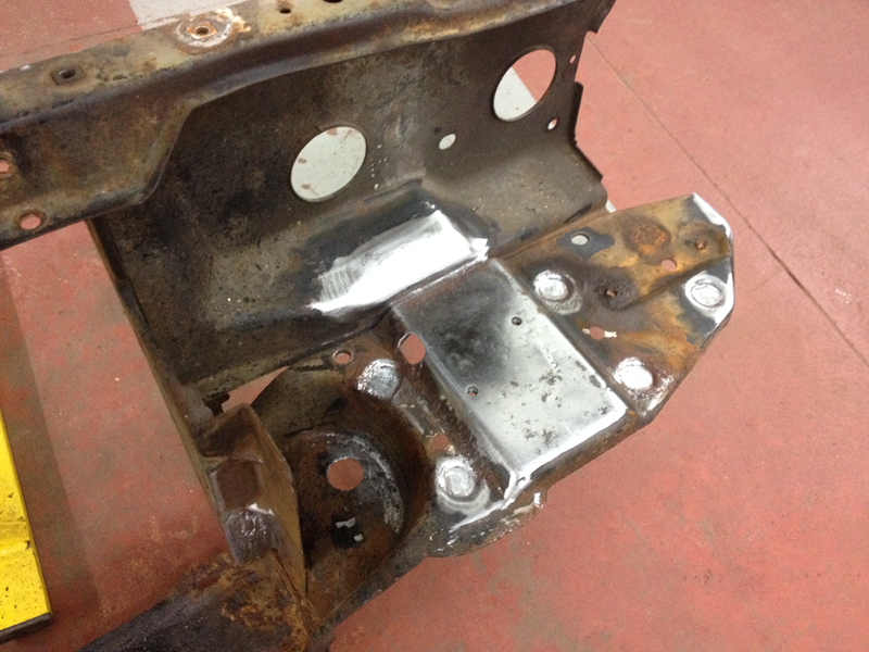
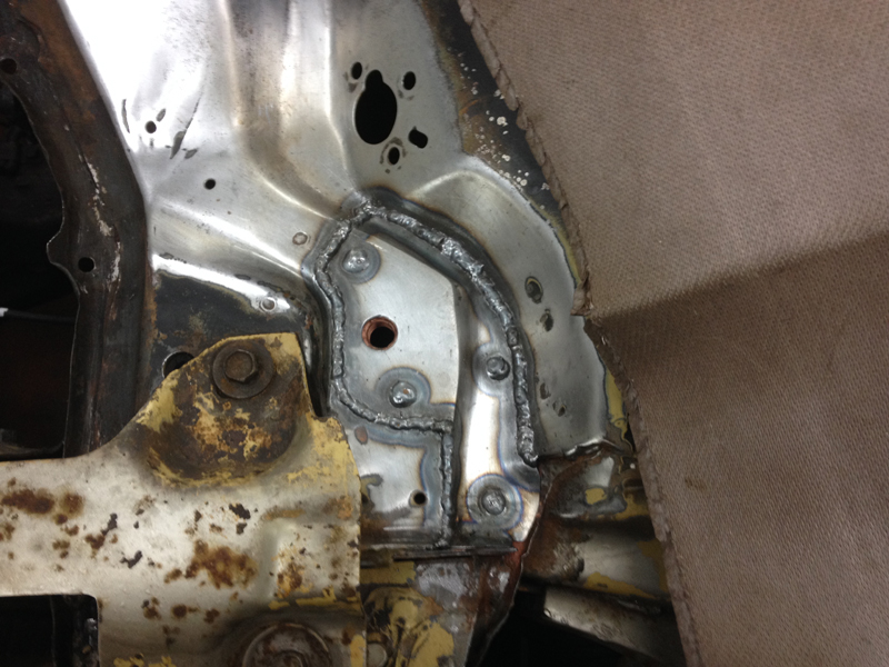
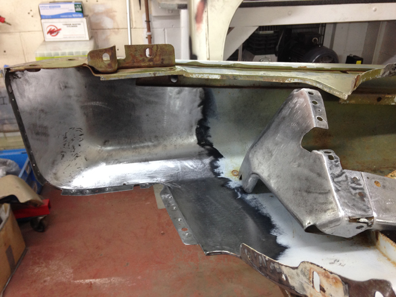
After a little more shaping, we were able to start welding the 2 sections together:
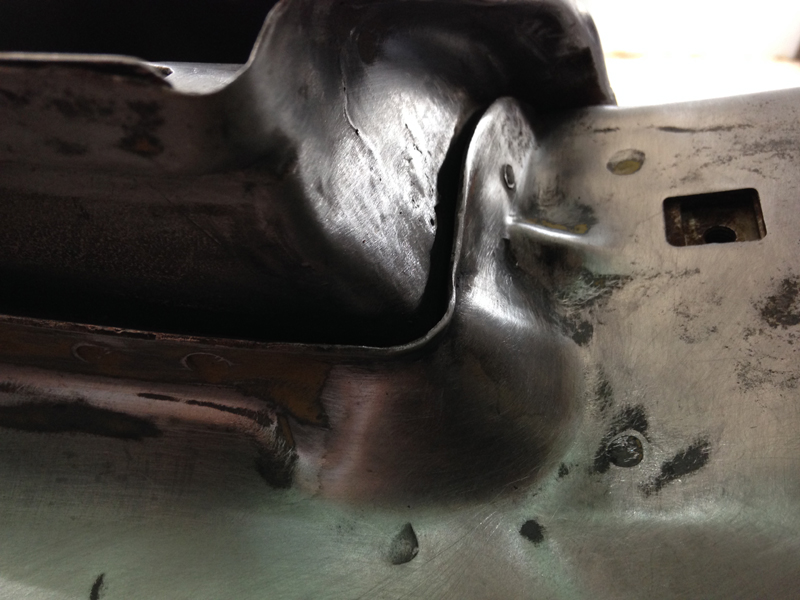
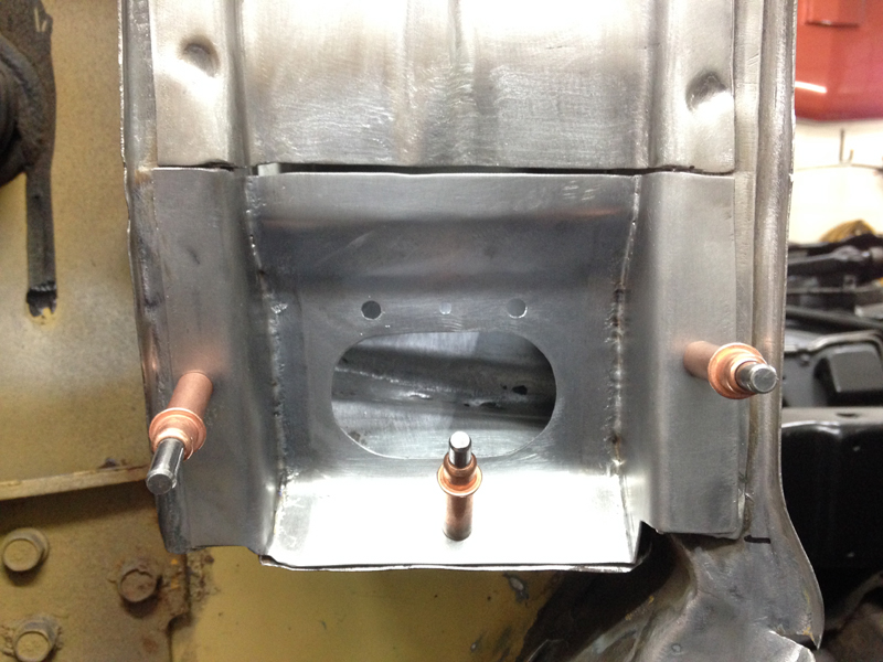
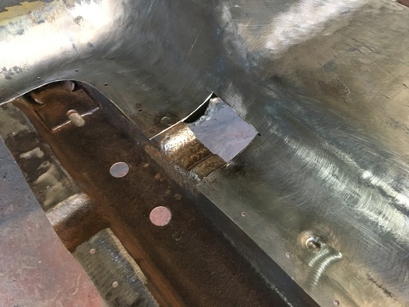
Even though the new section is designed for the battery tray that is sold with it, there are no fixing points on the rear of it:
So we welded some in place:
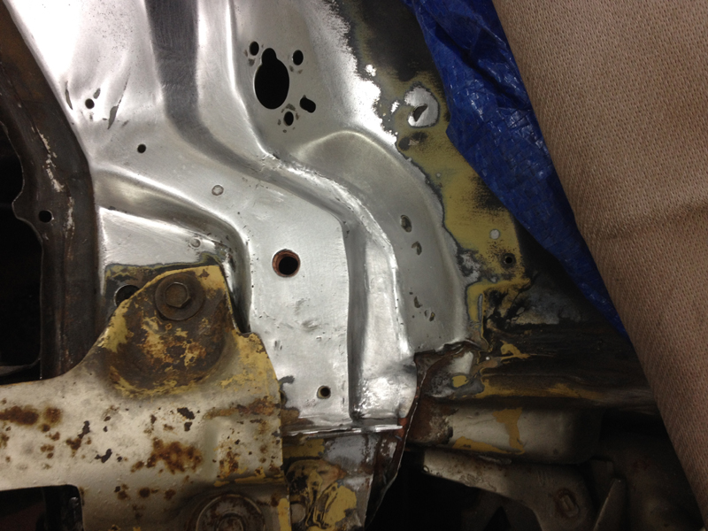
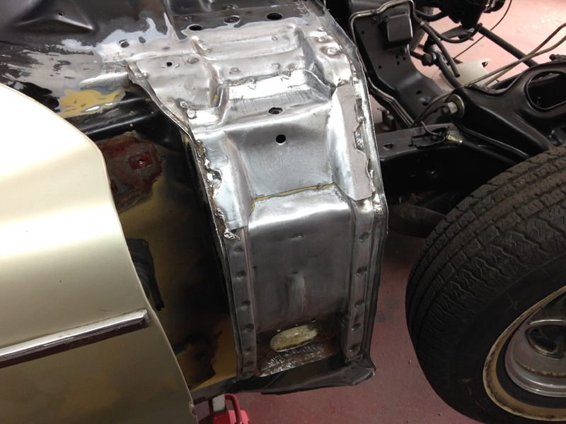
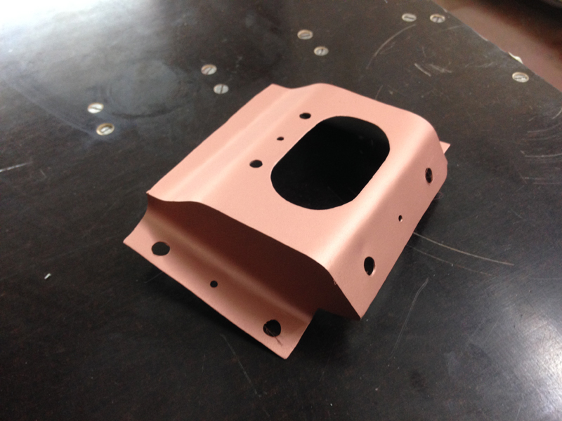
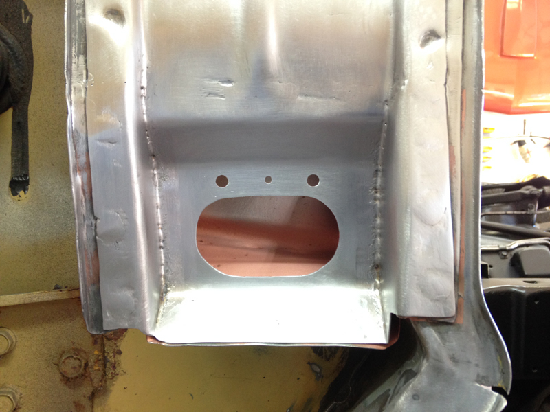
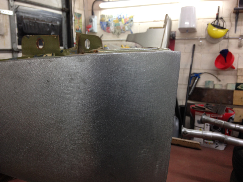
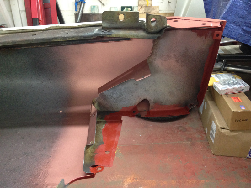
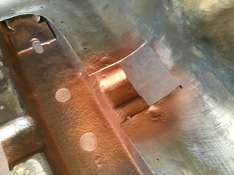
And then after cleaning all the welds up. The panel will need a little more work before its finished but at last it is a complete rust free item again that can properly and securley mount a battery in place on it:
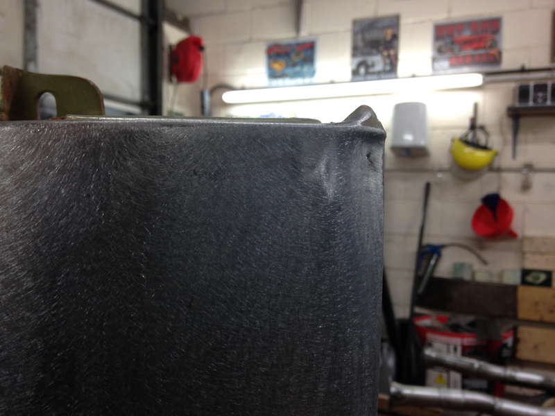
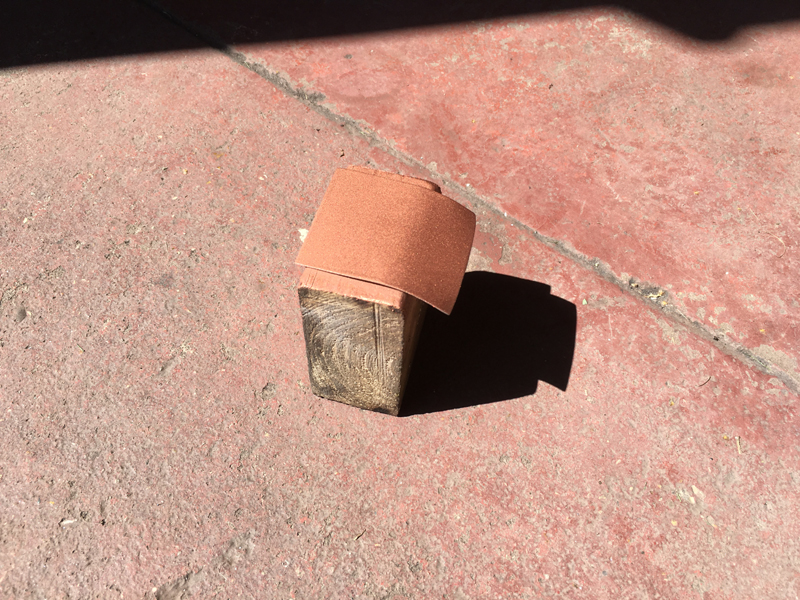
Over the years somehow this lip on the panel had gotten bent out of shape and damaged:
So we decided to spend some time straightening it back out:
This plastic lower wheel arch dirt shield mounts to the wheel well. Because the repair section is from a different vehicle it doesn't have the correct supports to mount it back on:
So we fabricated some small mounting tabs to support it:
And welded them in place:
The new battery tray had a tear in it caused by the stamping machine that presses the shape out of the flat piece of steel. We are not sure how this passes quality control during the manufacturing process, but no matter, we shall repair it:
First up, clean of the paint of the torn area:
Then weld it up and grind down the welds. The right hand side of the lip of the tray in this photo was also slightly out of shape so we straightend it out:
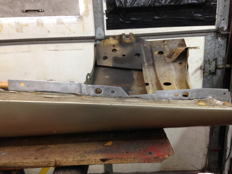
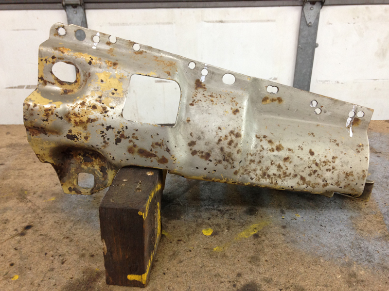
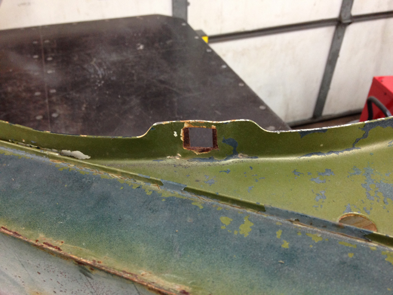
Up next was to remove the radiator core support to start making the repairs needed to it:
There were various rust holes in it and snapped off bolts in captive nuts for the original battery tray:
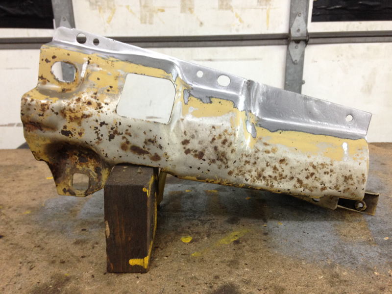
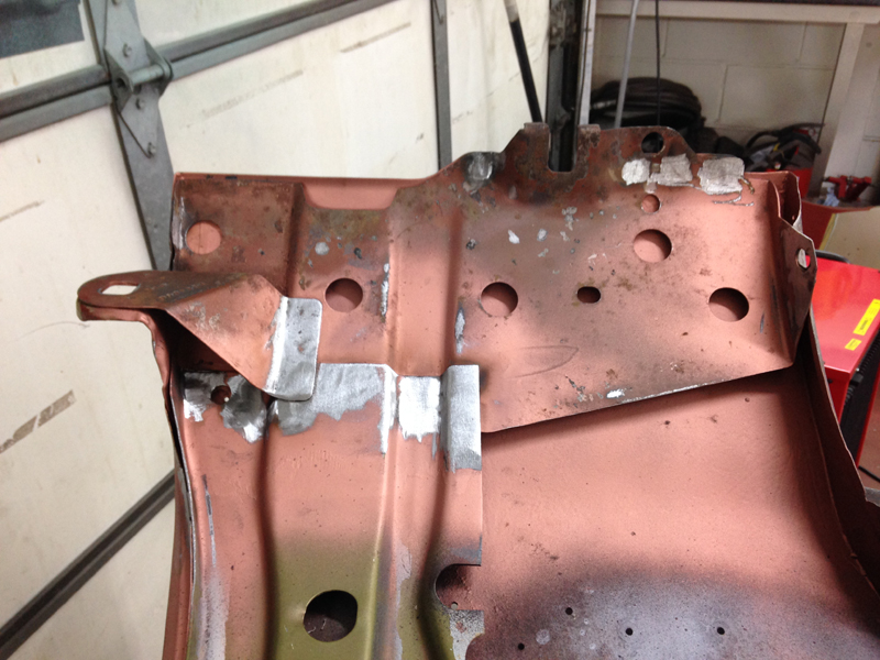
We repaired all of the rust and welded up all of the holes were the original captive nuts would have been since these will no longer be used:
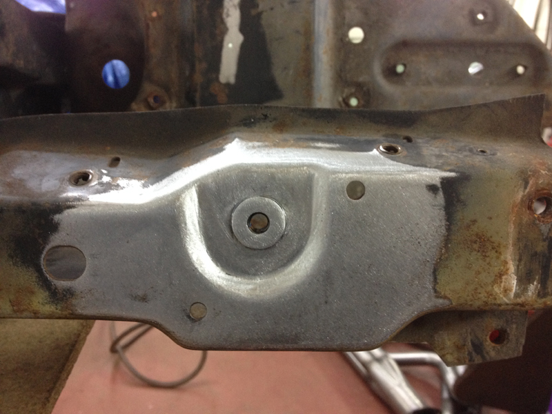
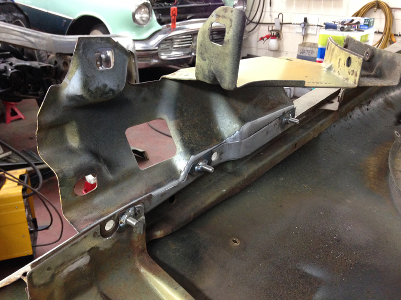
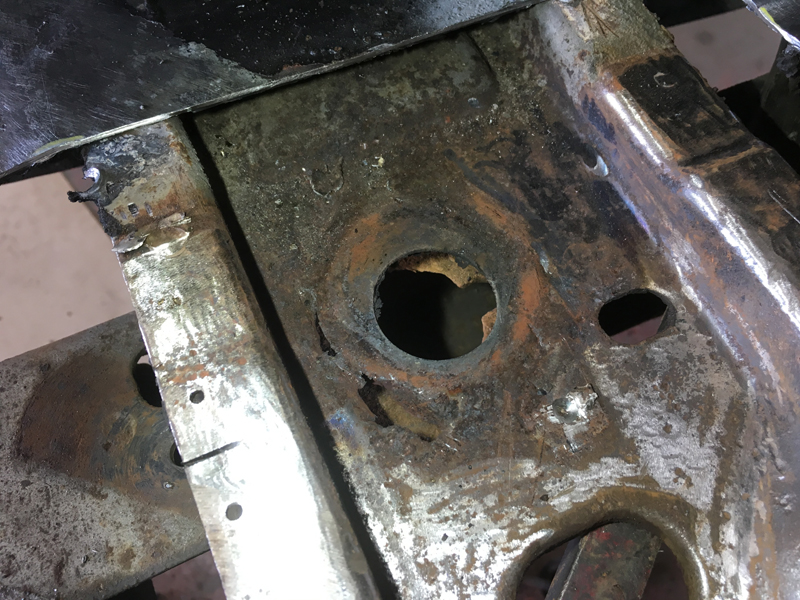
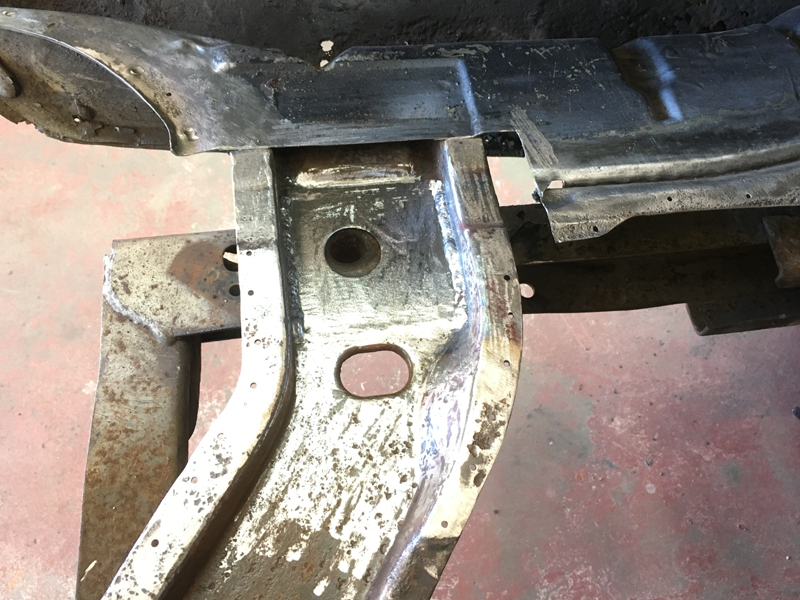
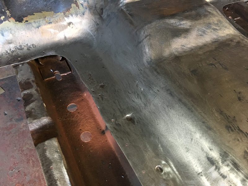
The last thing to repair on the core support were the fixing points for the bonnet bump stops. This is how the original fixing looks. 1 its messy and 2 both bump stops were siezed in place, 1 broke off attempting to remove it and the other pulled the thread out with it. New fixings are not available:
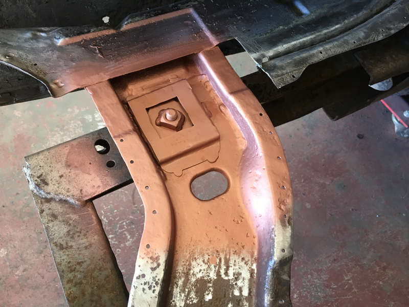
So we decided to make our own and weld them in place so that when the core support gets powder coated, they will get coated with it giving it a neater factory look:
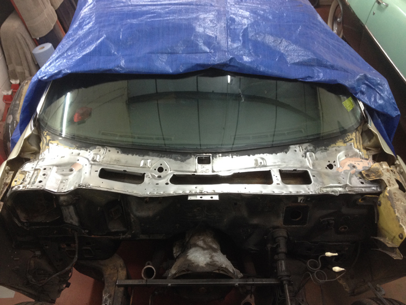
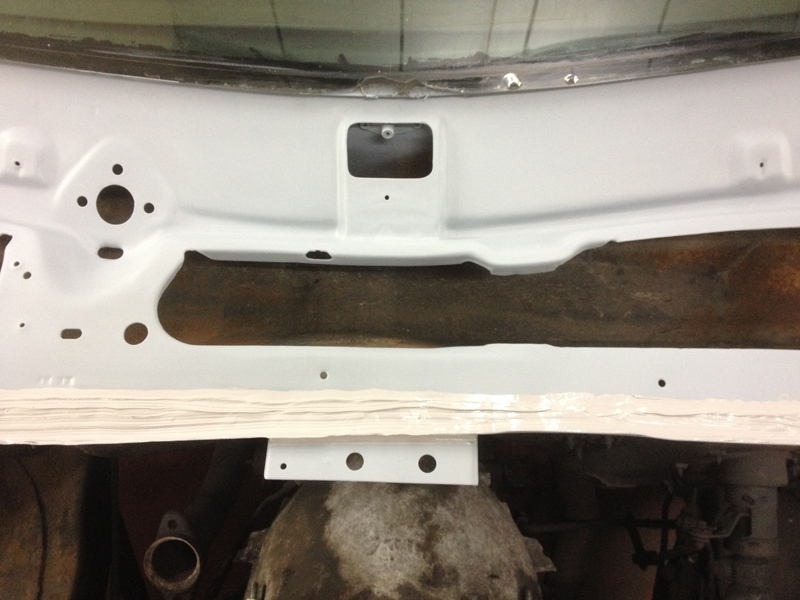
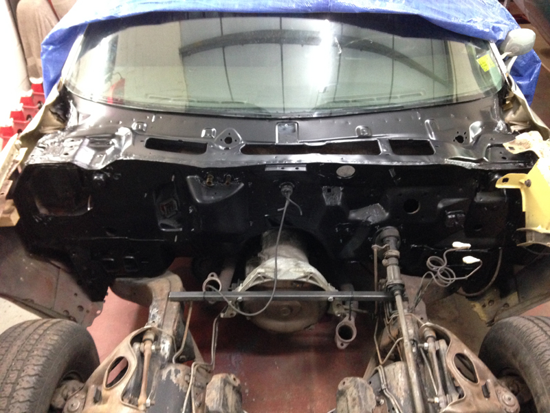
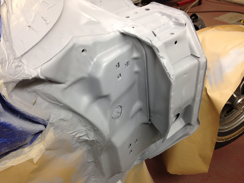
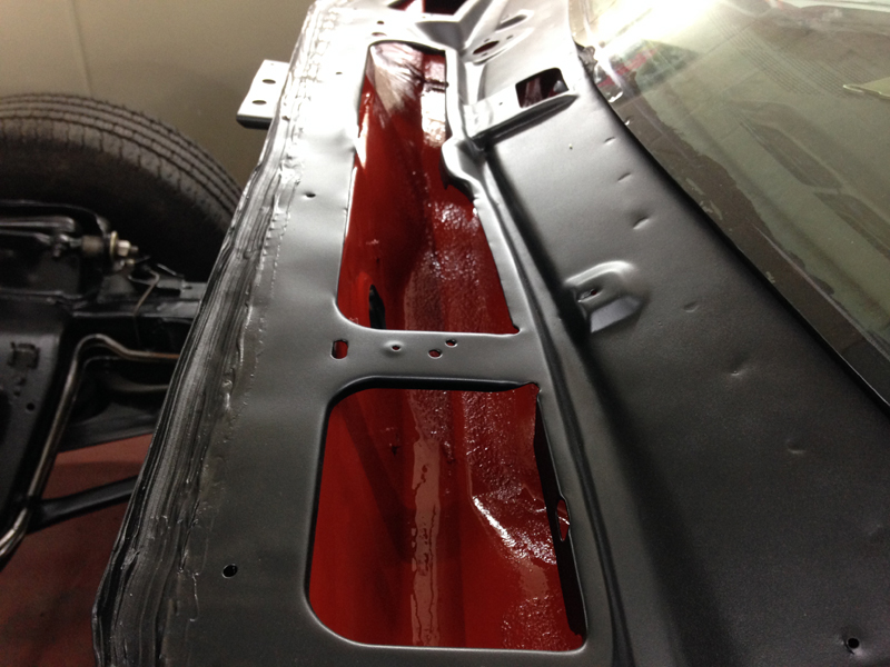
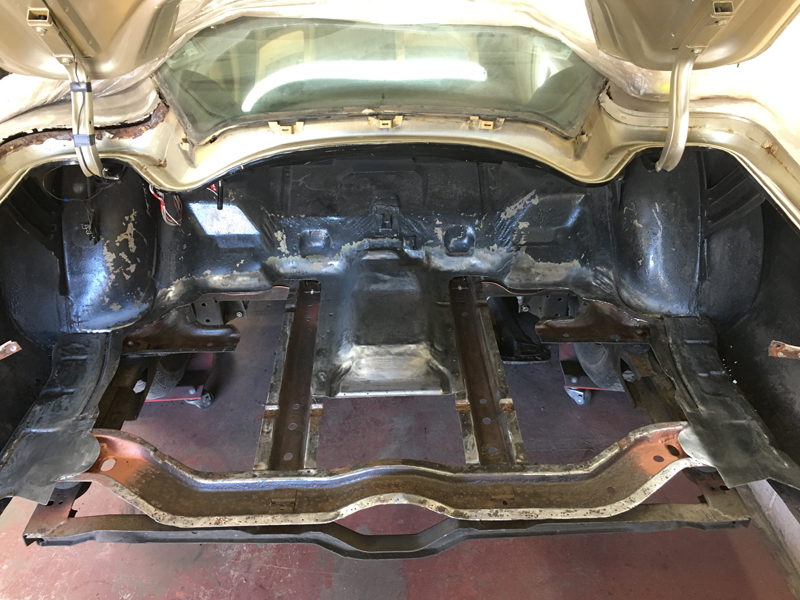
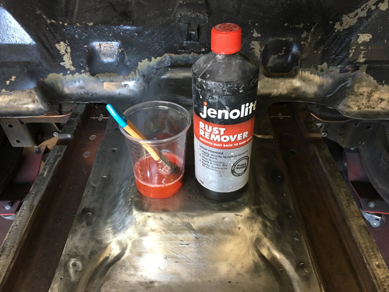
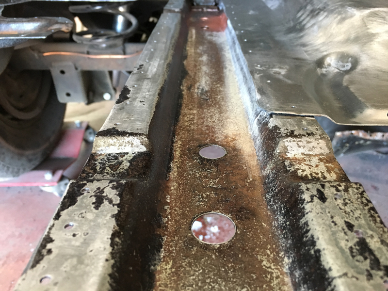
With the removable panels off at the powder coaters we could work on the engine bay. First up as to strip the rest of the items from the bulkhead and scrap the thick layers of grease and oil from the chassis rails:
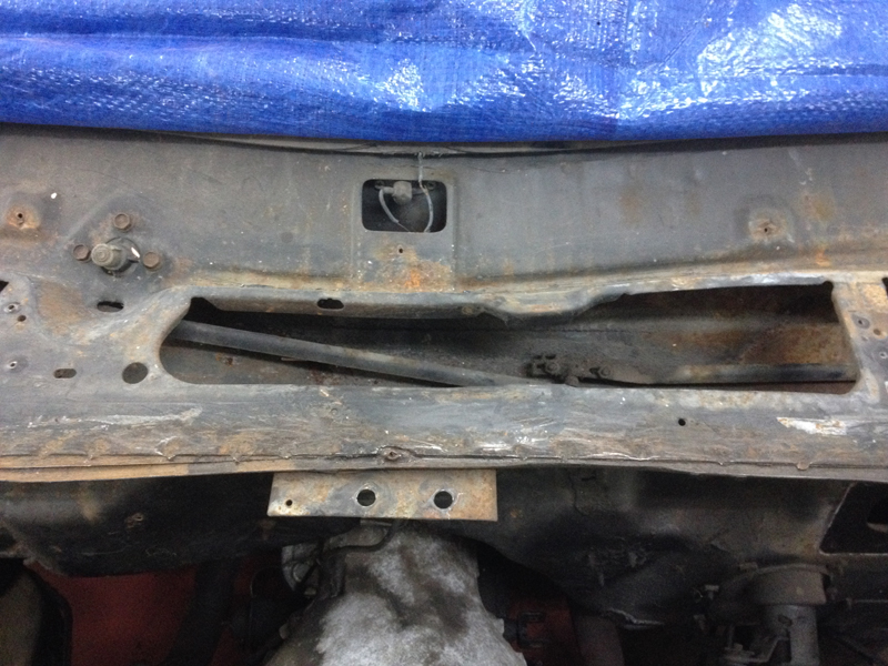
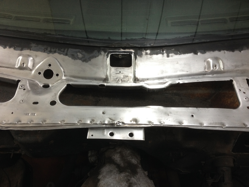
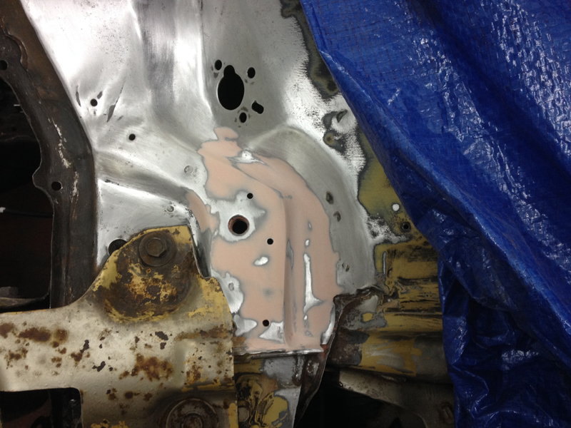
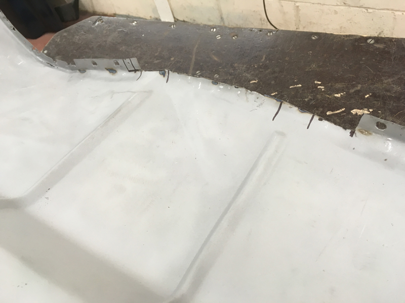
The scuttle panel area below the windscreen had seen better days,the paint was flaked off and the sealer all crumbled away and broken up, since we were planning on repainting the bulkhead we thought it would be a good idea to clean this up and repaint it at the same time:
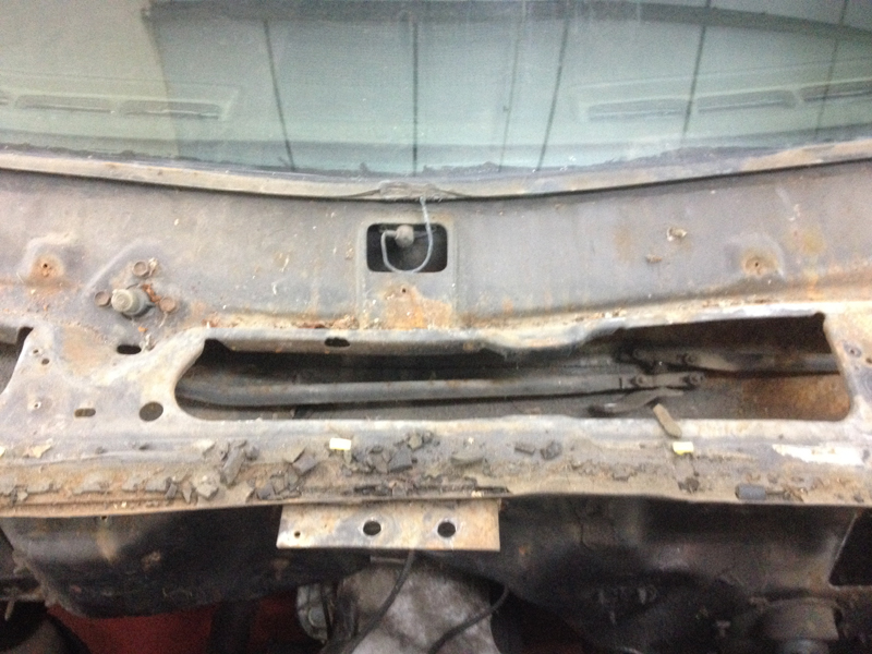
First scrape away all the loose sealer and paint and get rid of all the dirt:
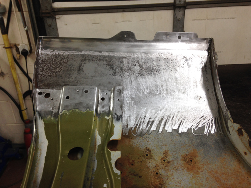
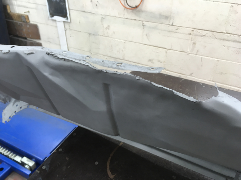
Then sand away at all the surface rust and loose paint until good clean metal is revealed:
Unfortunatly we found some bad rust on the drivers side which needed some attention:
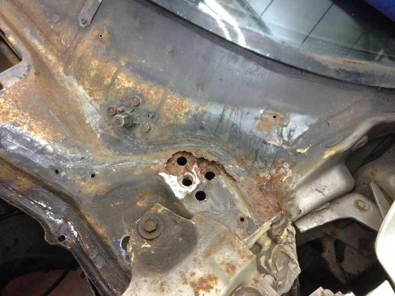
We had no choice but to carefully cut away the top layer of steel back to clean steel. The second layer below was heavily pitted but after using a wire wheel in a grinder to take the rust out the pits and some rust treatment on it the second layer wont need any further work:
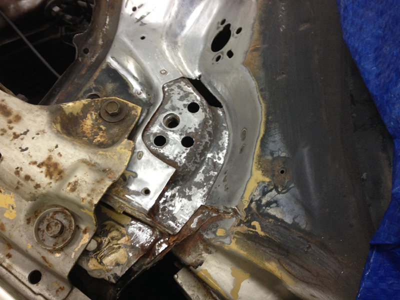
We then fabricated a repair section to be welded in:
And made holes in it for the spot welds:
We applied weld through primer to the top of the treated second layer and the underside of the repair section, this will help prevent any further rust build up between the 2 sections when it all back together:
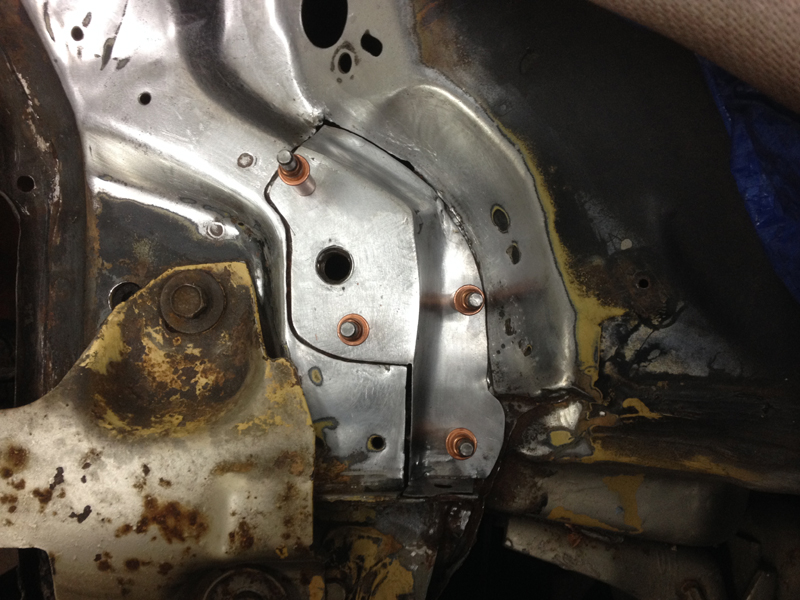
Next we welded the repair section in place:
And carefully ground the welds:
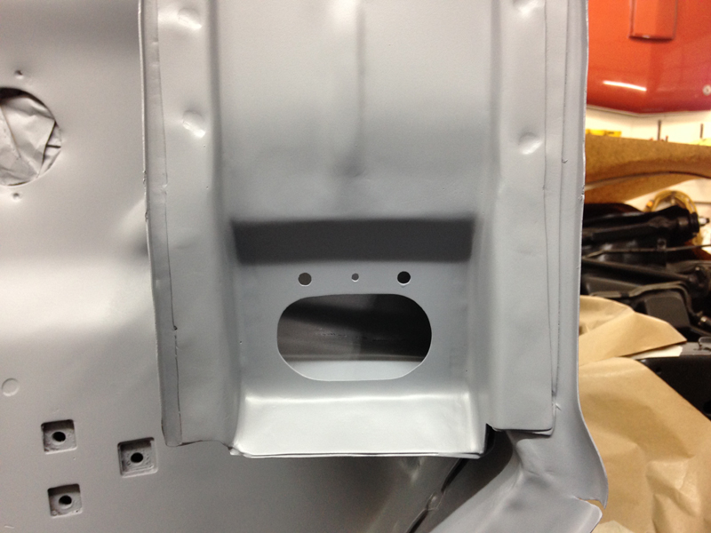
Drilled the 2 holes that hole the rubber seal in place which runs the full length of the scuttle and then applied some body filler to cover the welds and tidy the repair a little:
We had to carry out a similar smaller repair on the passenger side and then prepaired the rest of the scuttle area for some primer:
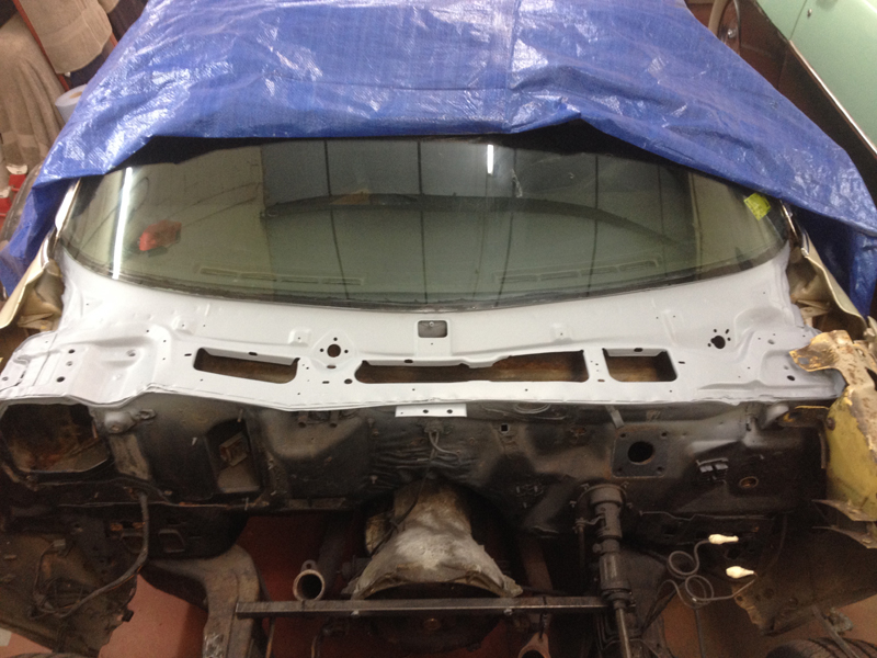
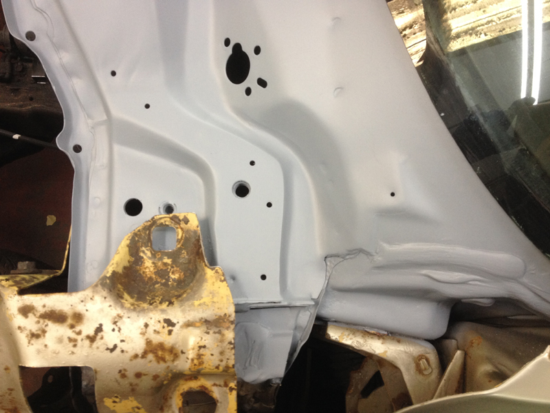
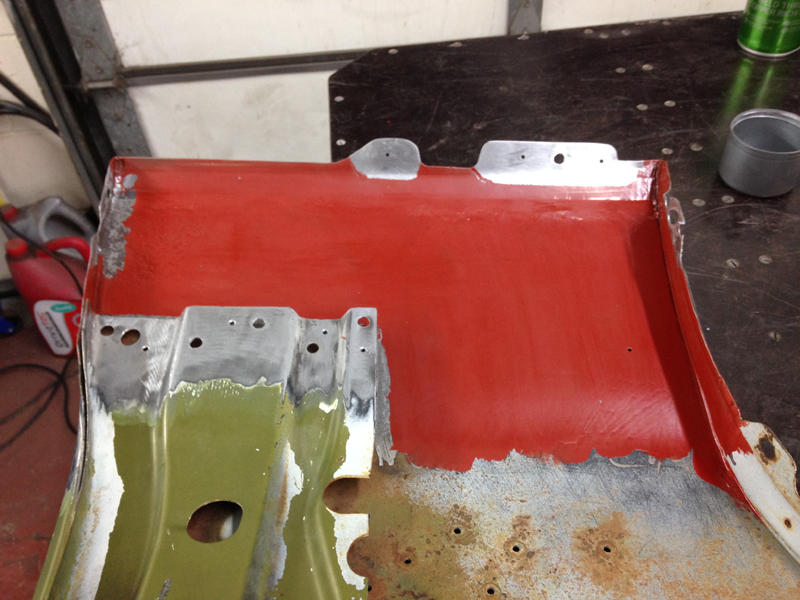
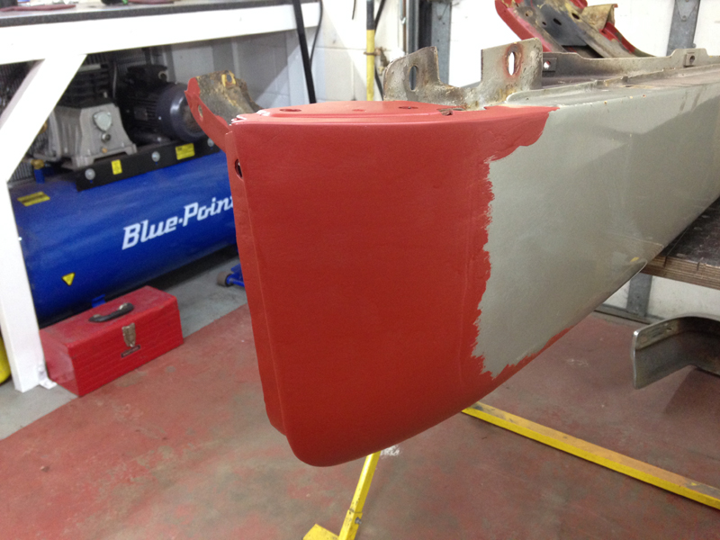
The applied some etch primer followed by some high build primer:
The repaired section of the drivers side came out real nice and if we hadn't have shown the photos of the repair work you wouldn't have known it had taken place:
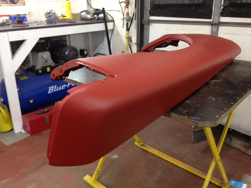
One the primer had dried we applied fresh seam sealer over all the seams and joins in the same place it was originaly applied from the factory:
Just another shot showing the side of the scuttle panel with the sealer applied. The sealer is over paintable so that when we paint the bulkhead and scuttle panel black it will all have the factory look:
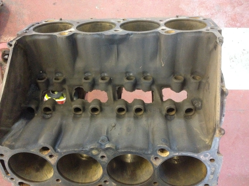
Before we sent the engine block away for the machining work to be done we thought it would be a good idea to do some work to the lifter valley. The casting is very rough and doesn't do much to help the oil drain back into the sump from the valley:
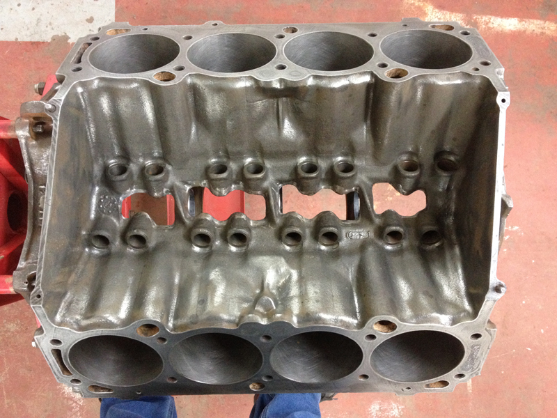
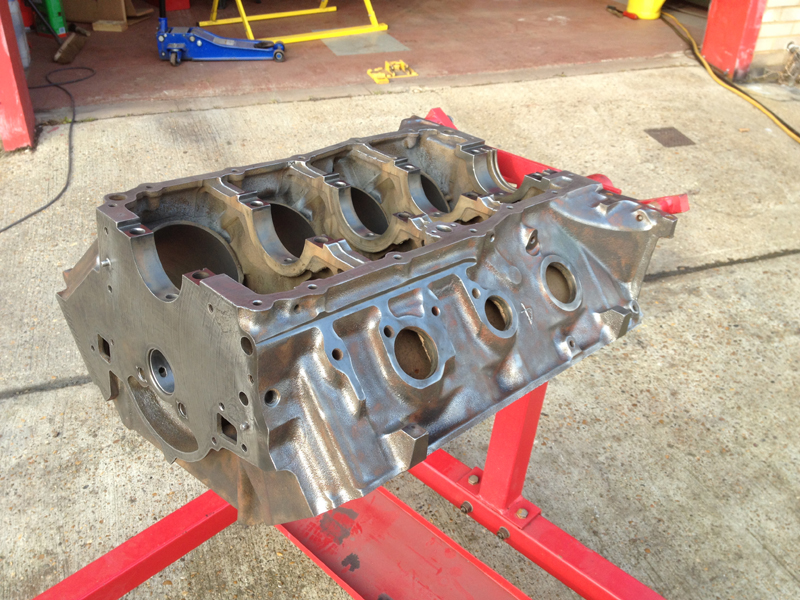
So we carefully ground the area smoother to remove all the rough casting and open the holes up a little. This doesn't affect the strength of the block at all and will help with oil flow. We done this before the machining work was carried out as the block was due to be washed out in an acid tank, this would remove all the metal grindings. This picture was taken once the engine had come back from engineers:
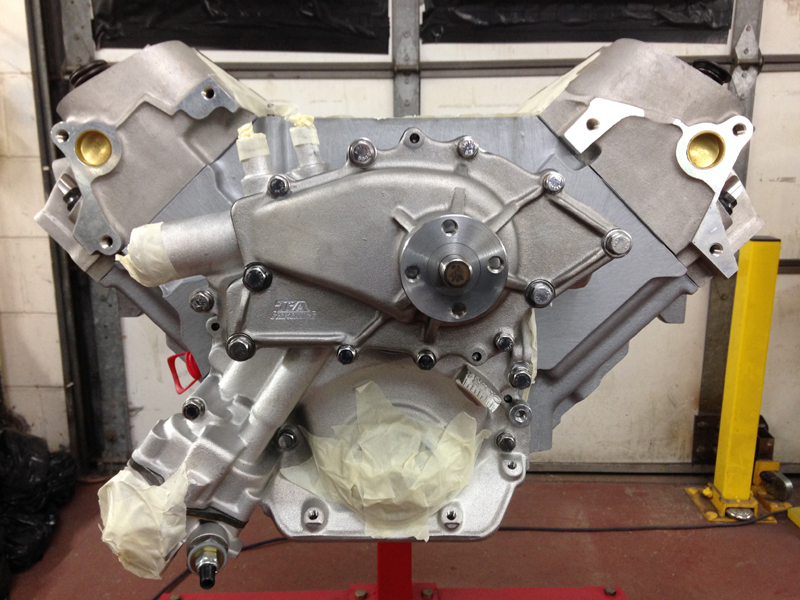
Unfortunatly as the paint on the block was so old and hard not all of it was removed during its wash, since we are going to be painting the block silver as per the customers request, we needed to remove the rest of the paint before continuing:
After alot of scrubbing and scrapping here is the bare block :
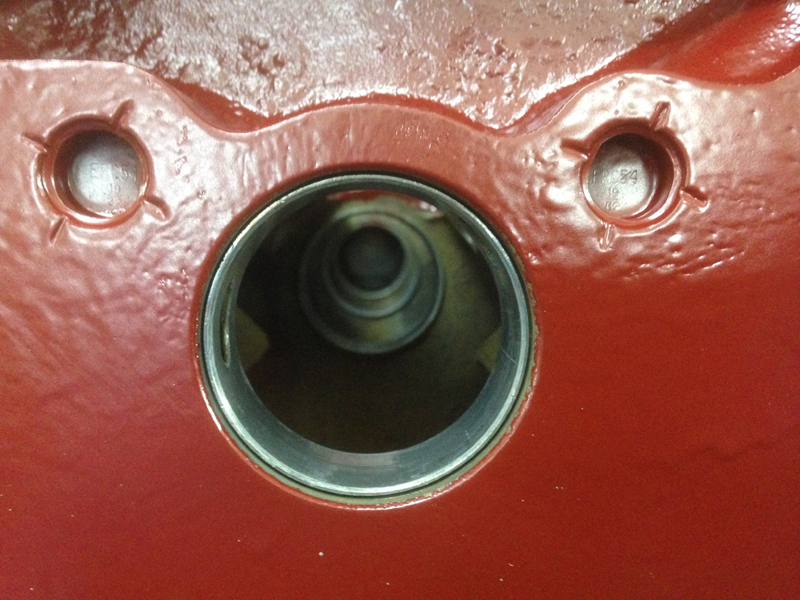
Before painting the block we installed the new core plugs so that they will get painted with the block for a cleaner look:
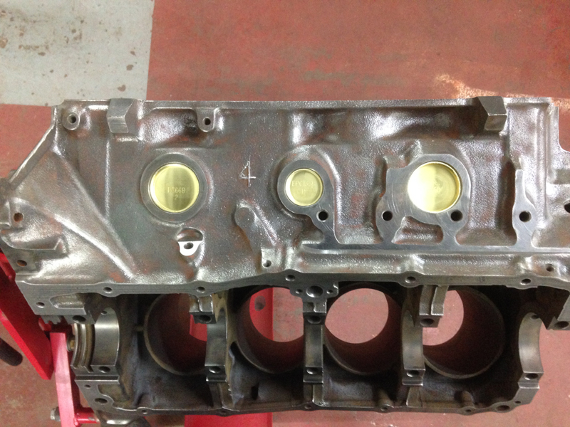
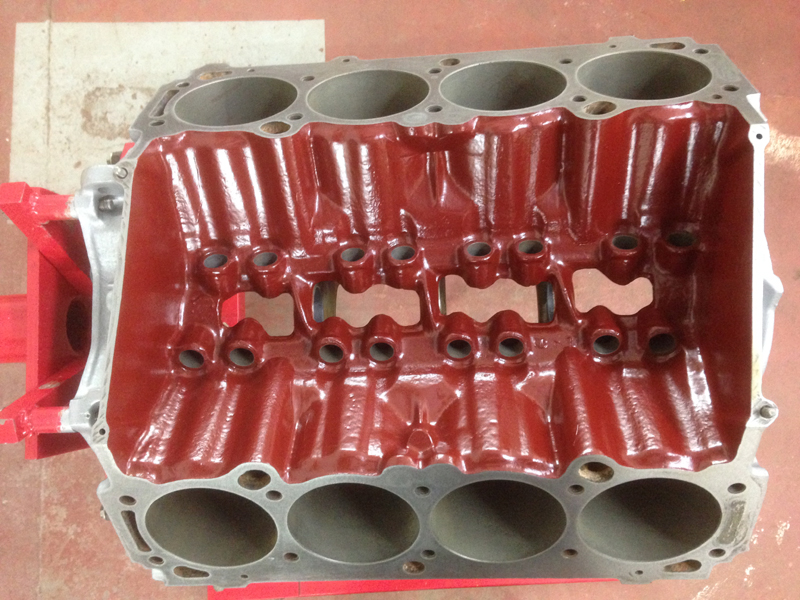
Once the core plugs were installed we prepped the block for paint. We painted the lifter valley and the area behind the timing cover with a special paint designed for painting the inside of engines. Its main purpose is that it is an oil resistant paint, the engine oil doesn't stick to the paint and helps with returning the engine oil back into the sump, another benifit of this is that because the oil won't stick to the block in this area there won't be any carbon build over over time:
And then painted the outside of the engine block with an aluminium coloured engine enamal:
Whilst the block was at the engineers they installed new camshaft bearings:
With the block painted we can now start to assemble the engine. First step, install the new crankshaft bearings, we had measured the crankshaft when we first removed it, it measured up perfect so the bearings were replaced with stock sized items:
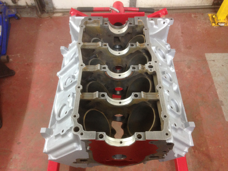
With the bearings in we also installed a new rear main oil seal, a neoprene version rather than the original rope type version as its harder wearing and will hopefully have a longer life than the rope type. We also lubriated the bearings faces with assembly lube so that the crankshaft is pre lubricated when its time to start the engine for the first time:
Before installing the crankshaft we washed it in the parts wash tank to make sure it was clean and using compressed air cleaned out all the oil ways, we also lubricate the crankshaft itself before installing it just to make sure its not installed dry at all:
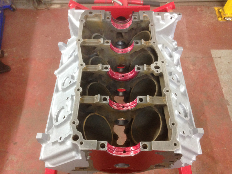
Next was to install the new pistons, we chose to use high compression forged pistons with valve releafs cut into them. We also used new piston rings and new main bearings:
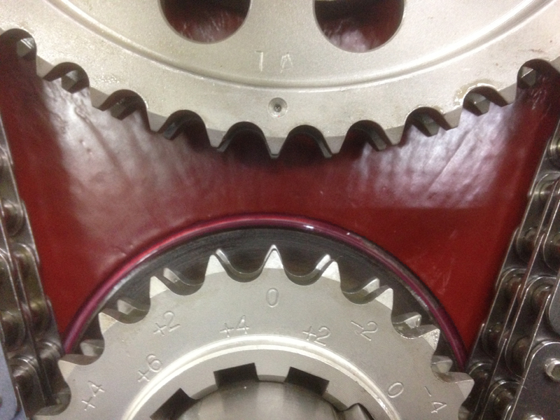
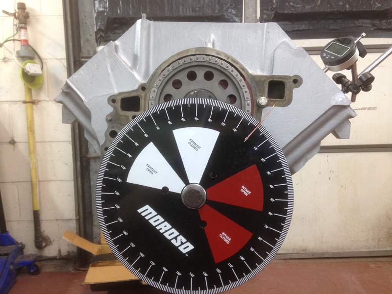
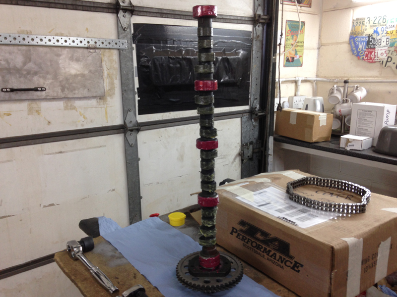
Next we temporary installed the camshaft, we say temporary as we have some checks to do first, so at this point we haven't lubricated the camshaft lobes, at this point we use a light coating of oil on the camshaft bearings just so that when we rotate it, its not being rotated dry. We also chose to run a double roller timing chain with a lower sproket with 9 different key way slots so that the camshaft timing can be set up accuratly:
When we installed the chain and make out initial timing checks we start on 0 and work from there:
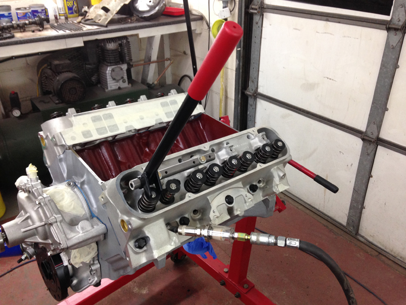
Next we installed a camshaft timing disc and set up a digital dial gauge to find the absolute top dead centre on cylinder 1. Using a piece of welding wire as a pointer we are able to make a note on the timing wheel, this is out starting reference point:
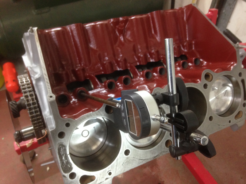
Next we install 2 of the camshaft lifters into the block and move the dial gauge onto the camshaft side of things. Ideally we want to run the dial gauge itself directly on the outer lip of the lifters but since this isn't possible in this case as there is note enough room in the lifter valley with out dial gauge set up we need to run of the centre of the lifter with an extension. To do this we converted the old lifters to solid lifters instead of hydraulic ones by removing the internals from them and packing them out with washers and then using one of the old pushrods on it as extension, as long as you have enough pre load set on the pushrod from the dial gauge and set the gauge at the correct angle the pushrod moves at this method is completly acceptable:
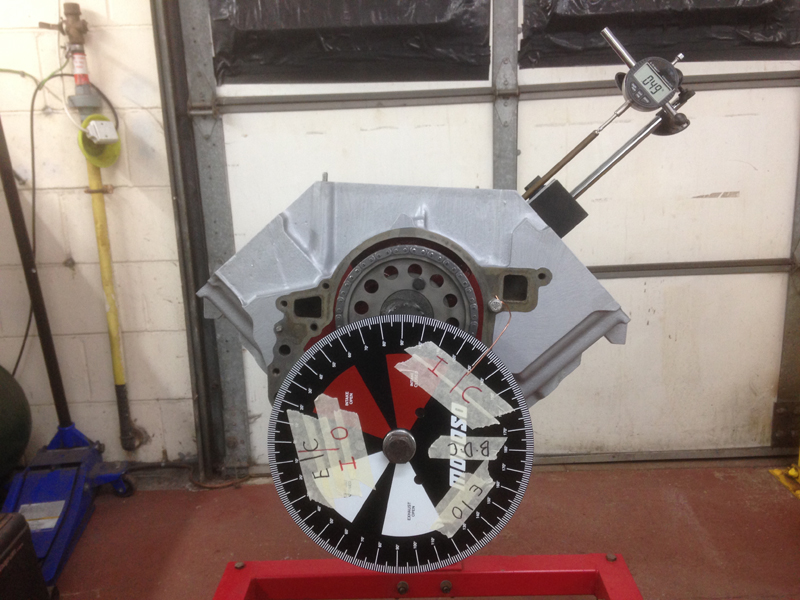
Now that we have everything set up and double checked we can make our readings, we do this to check several things, 1 that we have the correct camshaft that we have ordered and 2 to check at what point during the engines rotational cycle that the camshaft will open and close the valves. With any new camshaft you will recieve the correct figures for that camshaft to tell you at which point the valves should be opening and closing. Our intial readings told us that the camshaft would be opening and closing the valves too late by 4 degrees. With this information we know that we need to advance the camshaft by 4 degrees:
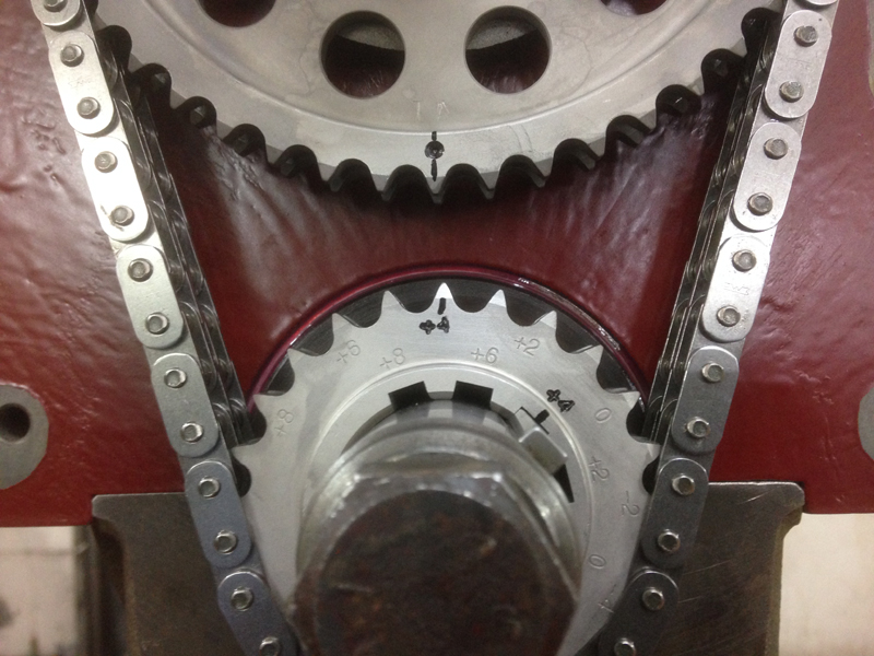
To do this we remove the crankshaft sproket and re-position it on the keyway on the +4 mark. When then carry out the whole checking procdure again from scrach and this time the the opening and closing points have moved by 4 degrees and now match the specs provided with the camshaft. We marked out timing sprokets so that when we take the camshaft back out in the future we know to put it back on using these marks:
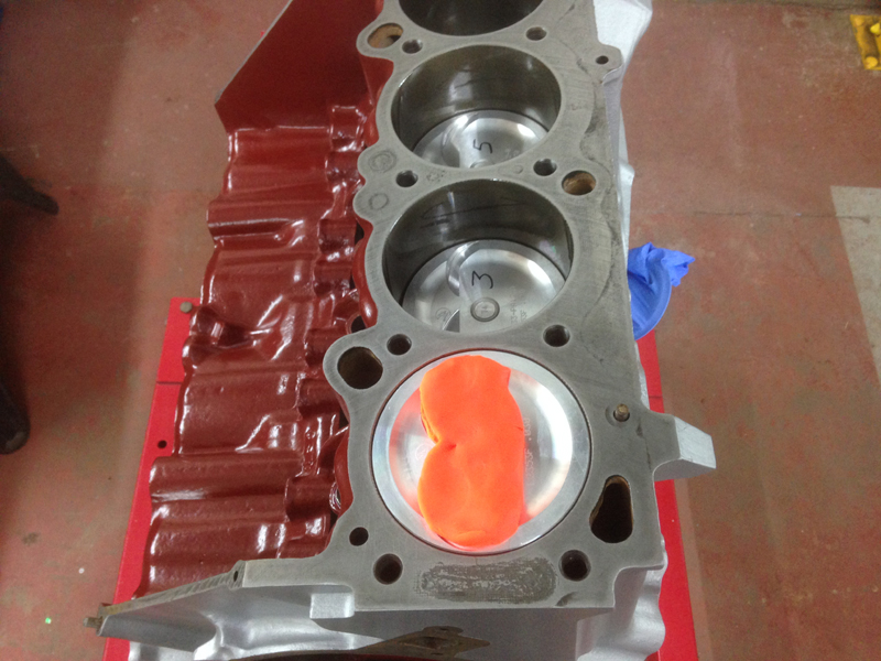
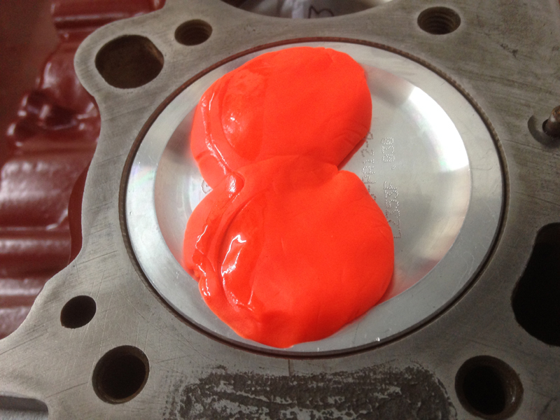
The next step is to check for valve to piston clearance, to do this we place some modeling clay on top of piston number 1, we make sure the top of the piston is clean and grease free, then oil the cylinder bore so that none of the clay can stick to the bore walls:
Then we bolt on the corrosponding cylinder head to piston number 1. We make a temperary head gasket from a piece of card that is the same thickness as the head gasket itself once its compressed to make sure our measurements are accurate. We also swap the 2 valve springs on cylinder 1 for valve checking springs, we do this so that turning the engine over take minimal effort and if there is a problem we can feel that something is wrong and then fit 2 of the original pushrods and the new roller rocker set up and adjust the rockers to suit:
Now we can turn the engine over 2 full revolutions so that the valves make contact with the clay on top of the piston. Then remove the cylinder head to check we made contact:
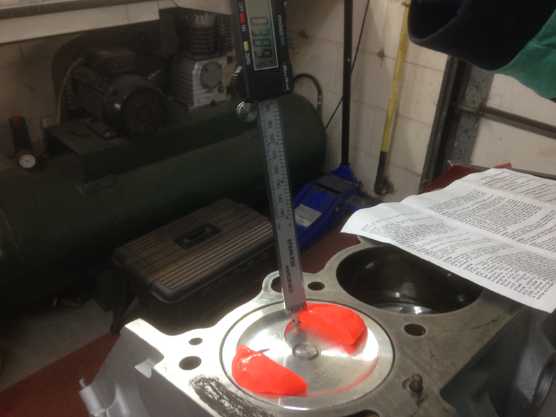
Now we can take our measurment, to do this we cut the clay in half and remove the centre section, then using a vernier gauge, check from the point were the valve made its deepest impression in the clay to the top of the piston. The clearance specs are provided with the new camshaft and we can then confirm that we have plently of clearance:
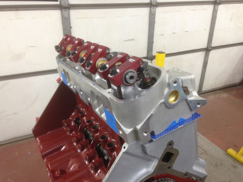
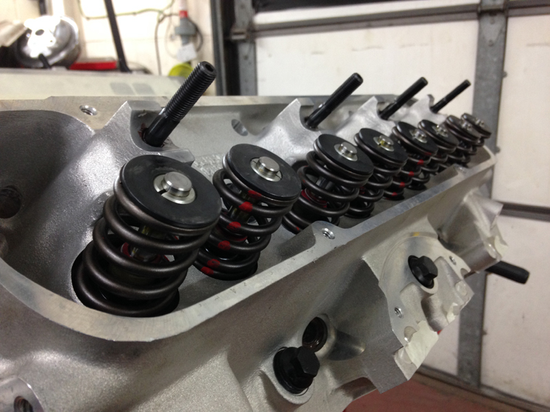
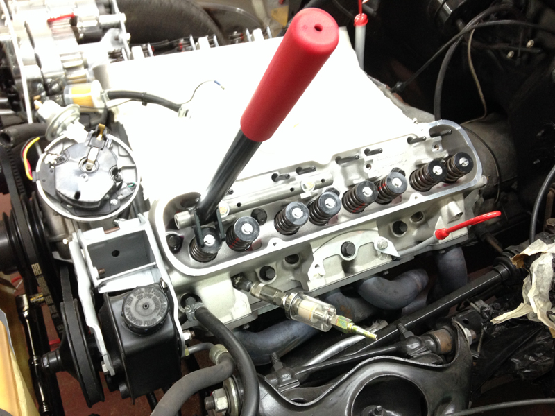
The next step is to properly install the cylinder heads. These are brand new items from TA Performance. They are their stage one aluminium cylinder heads. Not only is there a massive weight saving in using these heads but they are also a massive improvment in design over the original heads and have larger ports and valves. We install the heads using ARP bolts and new gaskets:
The next stage is to check for the correct length of pushrod we need to use. Some of the original pushrods were slightly bent and using a different to factory cylinder head and roller rocker assembly alters the height of the point were the pushrod meets the rocker, even though the rocker assembly do allow for adjustment its best to use the correct length pushrod to start with and then use the adjustment in the rocker to fine tune the preload on the lifters. To do our checks we install one of the new lifters, an adjustable pushrod checker, and then the rocker assembly. Note that we are doing our checks on one of the cylinders with the correct valve springs installed, if we did our checks on the cylinder with the checking springs, the springs are so weak that we would begin to open the valve before preloading the lifter. First we set the rocker adjuster to its optimum position, then wind out the adjustable pushrod to preload the lifter with the correct ammount of lift, then all thats left to do is remove the pushrod, measure it and order the new pushrods:
Whilst waiting for the new pushrods to arrive we turned our attention back to the car itself to finish painting the bulkhead and scuttle panel. First we needed to prepair the bulkhead and the primed scuttle panel:
Then after masking everything up we painted both areas in satin black as per the cars factory finish. All that was left to do was remove the masking paper and see how it turned out:
Now that the rest of th engine parts we had been waiting for had arrived we could continue with the engine. First was to pull the camshaft back out, lubricate it and then install it for the final time:
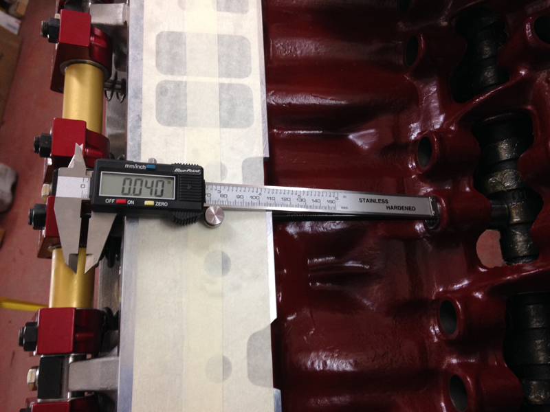
Then we done a quick check to make sure that the new pushrods we had ordered were the same spec as the ones we has asked for, with the roller rocker set up as per the manufactures requirments the preload on the lifter should be between 0.030-0.060. We have 0.040 which is perfect:
Next we lubricated and installed the rest of the new hydraulic lifters:
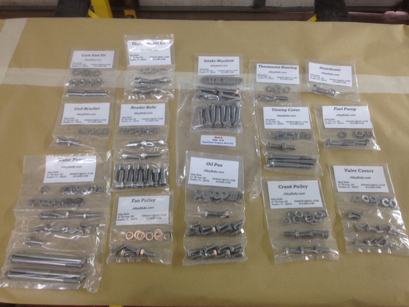
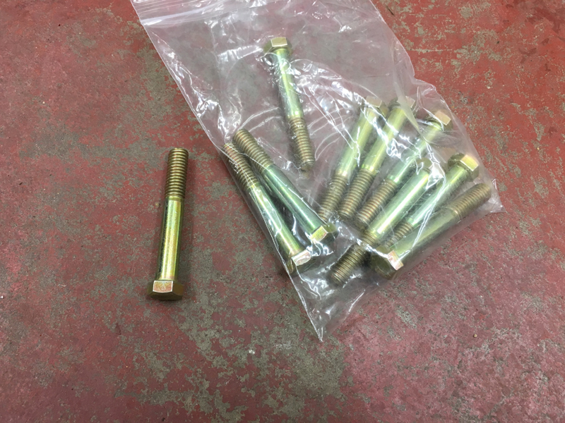
We ordered a polished stainless steel fastener kit for the engine so that everything looks good and stays looking that way:
Then installed the new timing cover and water pump:
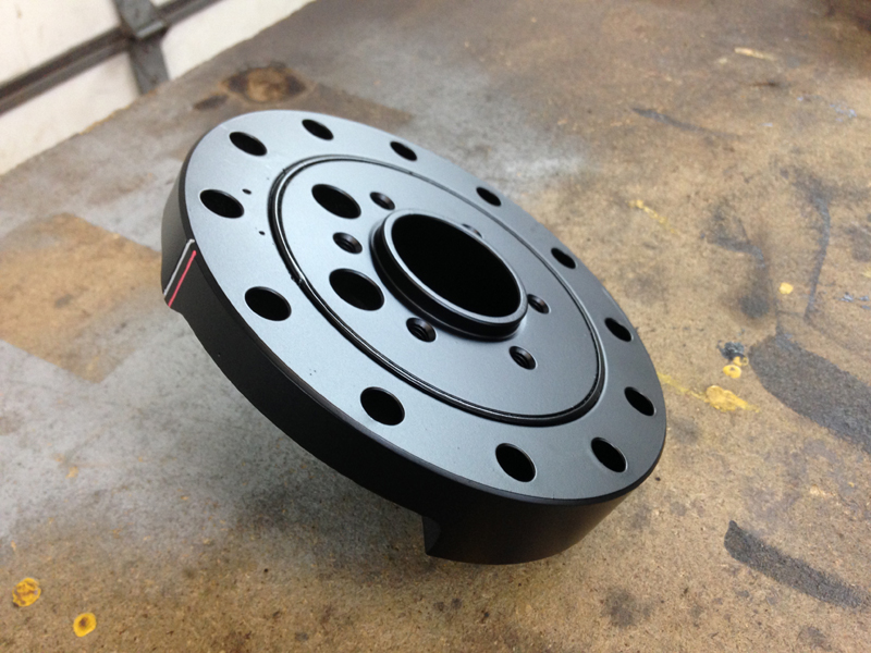
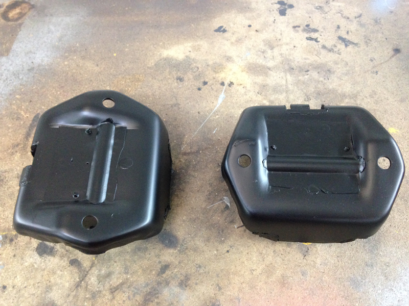
The harmonic balancer and engine mounts all needed replacing, the new ones came in unpainted so we painted them and highlighted the timing marks on the balancer. The red mark is TDC and the silver mark is 4 degrees BTDC:
and the mounts:
We needed to remove the setting up valve springs and re-install the correct valve springs for cylinder one as well as remove the inner valve springs from the rest of the cylinders so that we can break in the new camshaft and lifters when starting the engine for the first time. Once they are broken in we need to then re-install the inner valve springs. So that we can do this without removing the cylinder heads each time we used a tool that lets us do it with the heads in place, using compressed air through the spark plug hole to stop the valves falling into the cylinders with the springs removed:
The correct out valve springs back on cylinder one and the rest of the cylinders with only the outer springs installed:
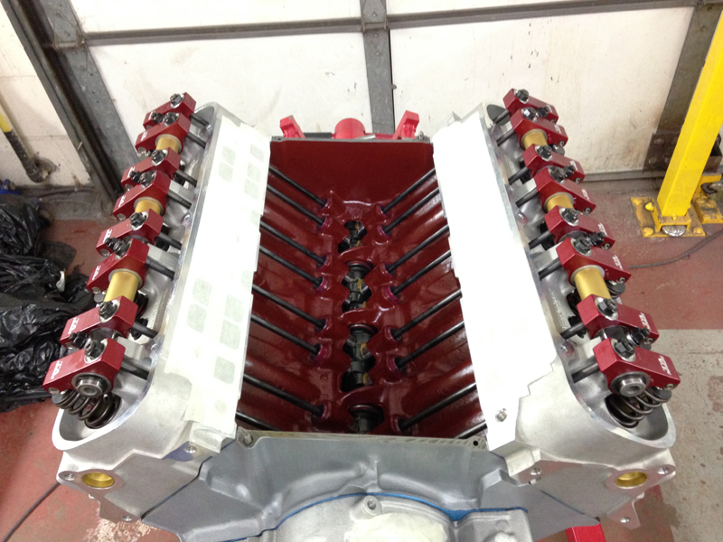
With the springs all done we then installed the new pushrods and roller rockers and set the preload on the lifters:
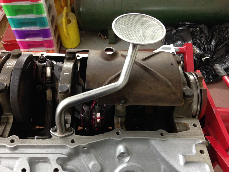
We installed a new oil pick up tube:
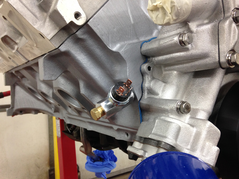
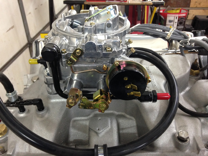
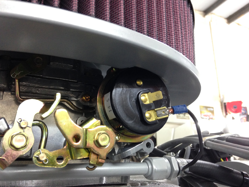
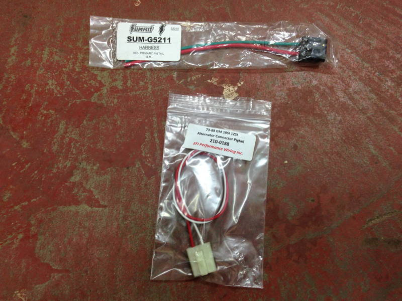
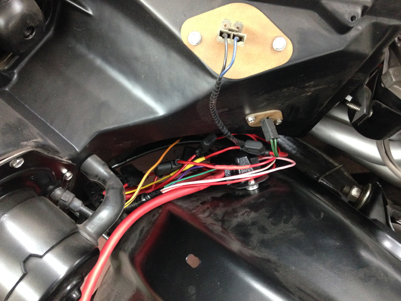
The new carburettor has an electric choke set up. To opperate the choke we wanted to use an oil pressure switch so that the choke doesn't start to open until the engine is running, as opposed to the other set up, that is once the ignition is turned on the choke starts to open regardless of weather the engine is running or not. The 3 pin set up allows us to opperate a component (the choke for example) and also still opperate the oil pressure warning light on the dashboard. We also used an adaptor that allows us to connect a mechanical oil pressure gauge to the engine at the same time without having to remove the switch so that we can monitor the engines oil pressure when running in the engine:
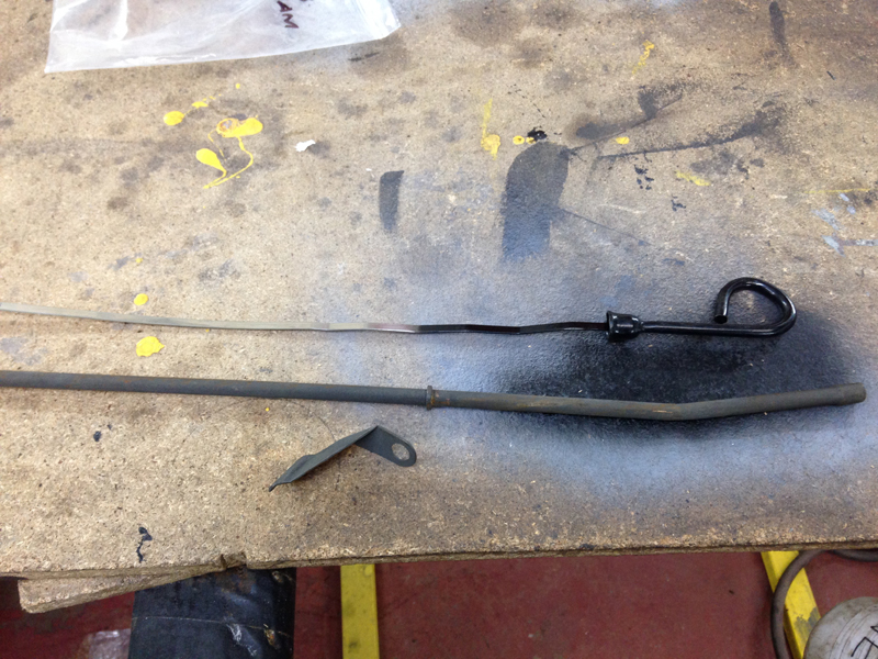
When using the aluminium cylinder heads you need to use a different dipstick set up. The kit comes with a new tube, stick and bracket which needs welding on:
The bracket looked like it would cause a clearance issue for the spark plug wire on the cylinder:
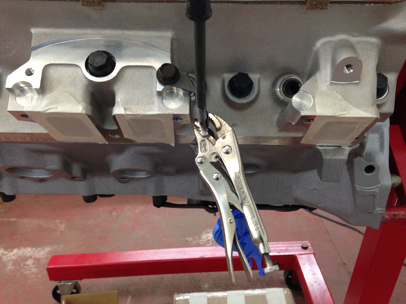
So we made a new bracket that gave us clearance:
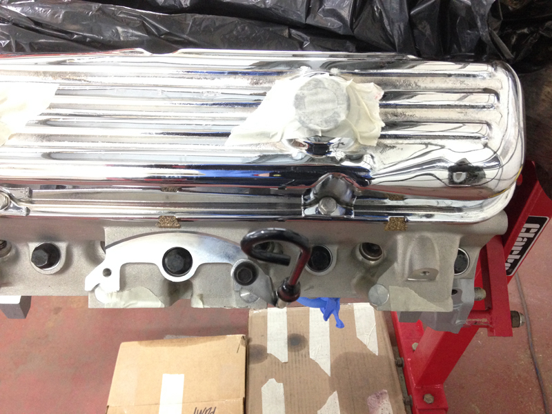
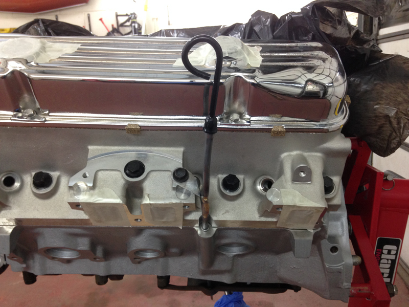
Then tack welded it onto plac,e then finished it by brazing the rest of the join. If you weld it together fully, the weld penetration on the inside of the tube will stop the stick going into the tube properly:
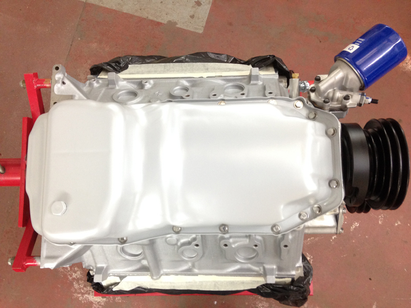
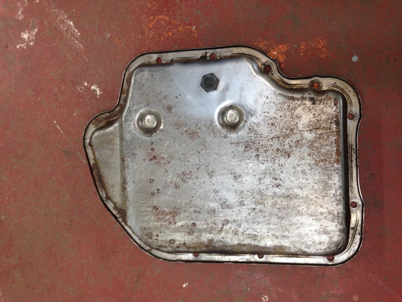
We had the oil pan sand blasted and powder coated along with the rest of the engine brackets and bolt on parts. We had to clean off the excess dirt and sand blast from the inside the pan before fitting it:
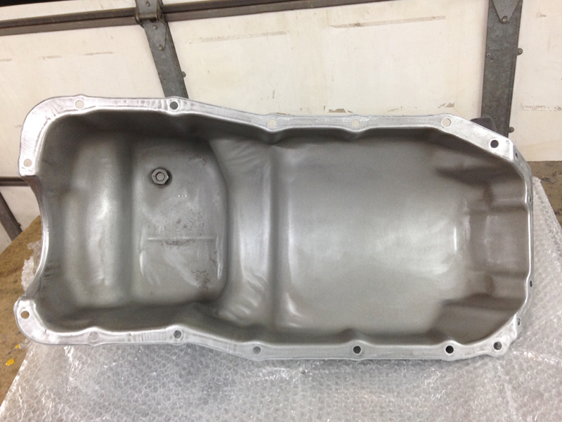
Then installed the pan with a new gasket and stainless bolts from the bolt kit:
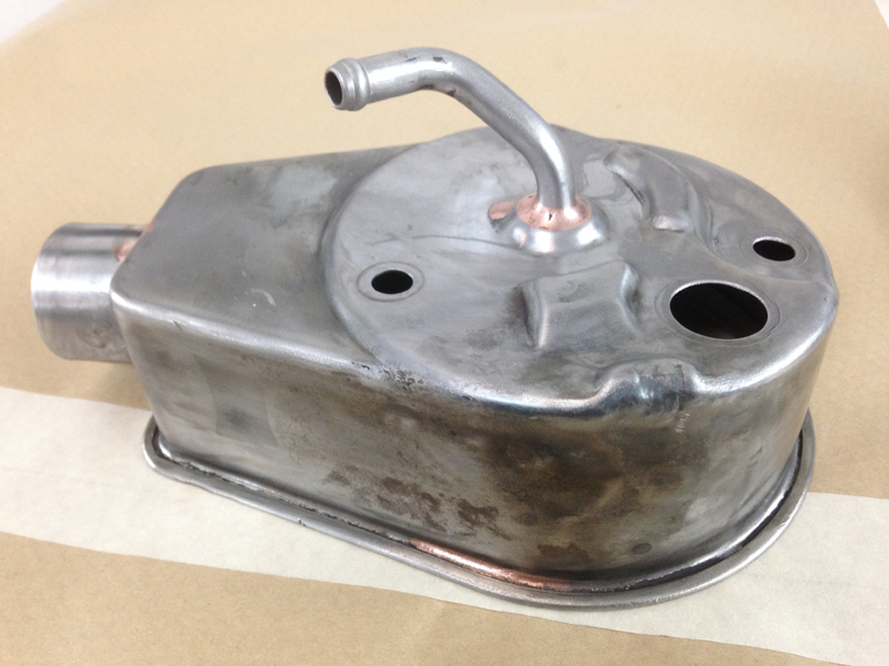
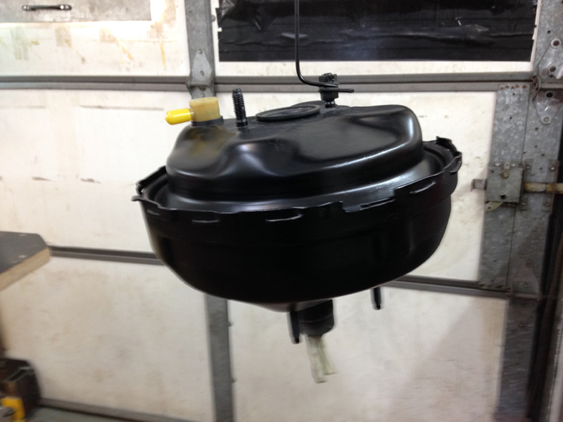
The power steering pump assembly had seen better days and had been leaking, so we planned to strip it, clean it, replace the seals and paint it:
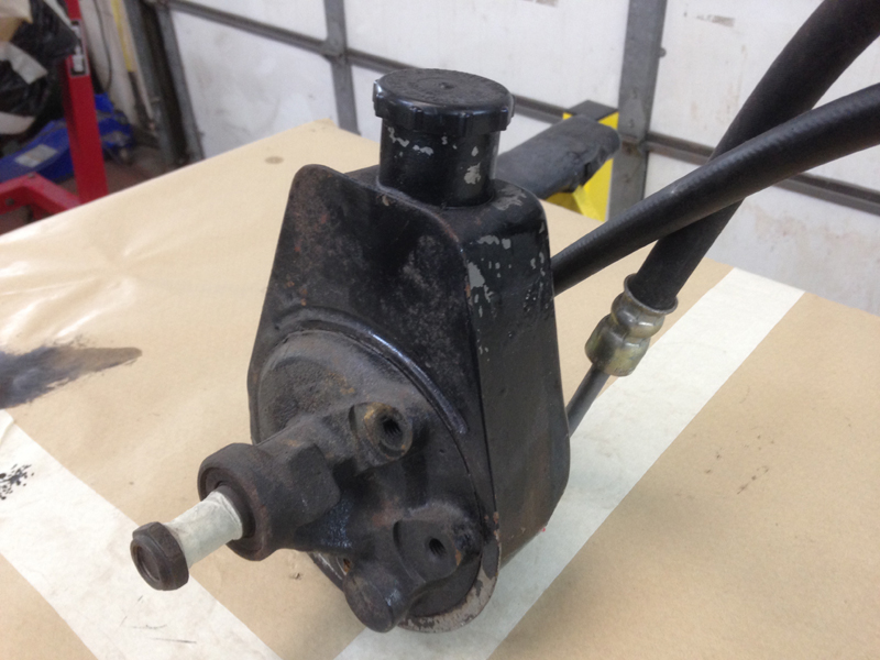
The tank body had lots of dents in it and flaking paint with rust under it:
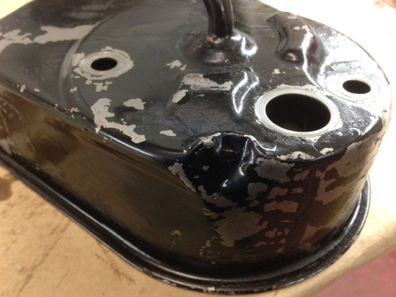
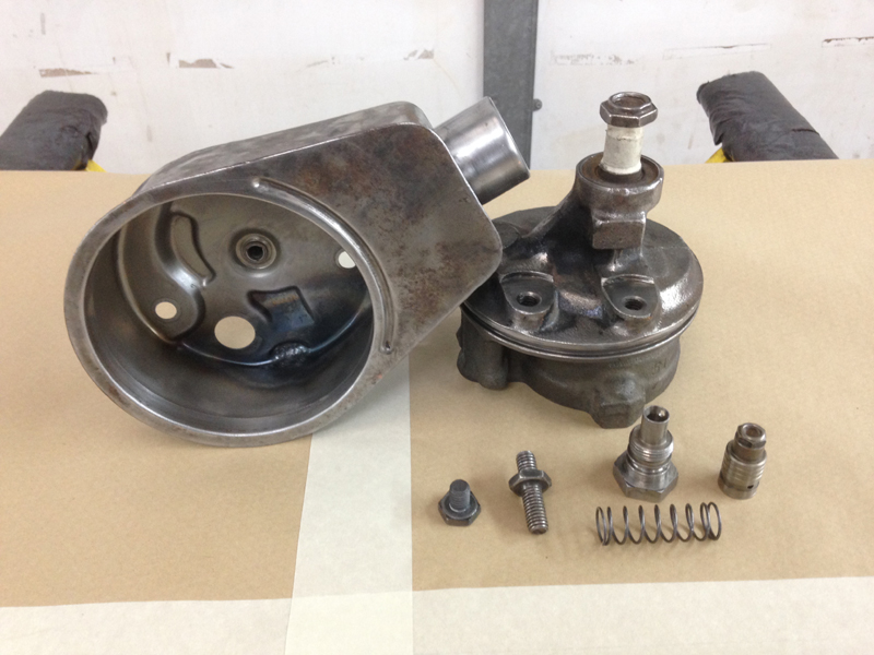
We stripped it back to the metal and knocked out the dents as best we could, access to some of the dents from inside the tank was limited:
The assembly stripped, seals removed, paint removed and cleaned ready for re-assembly:
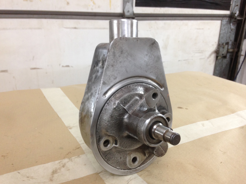
Then all back together and prepped for paint:
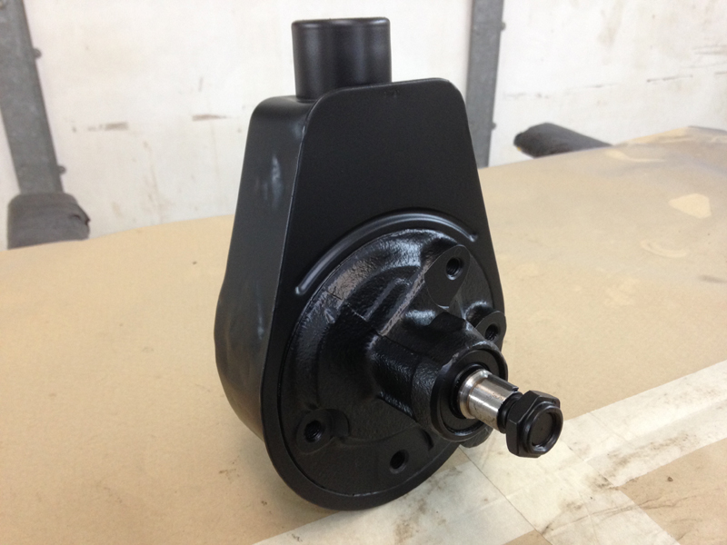
Then painted satin black ready to be re-fitted back onto the engine:
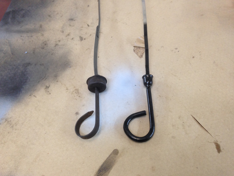
We wanted to paint the dipstick handles red so they stand out a little, so that checking the fluid levels is easier. This is what we started with:
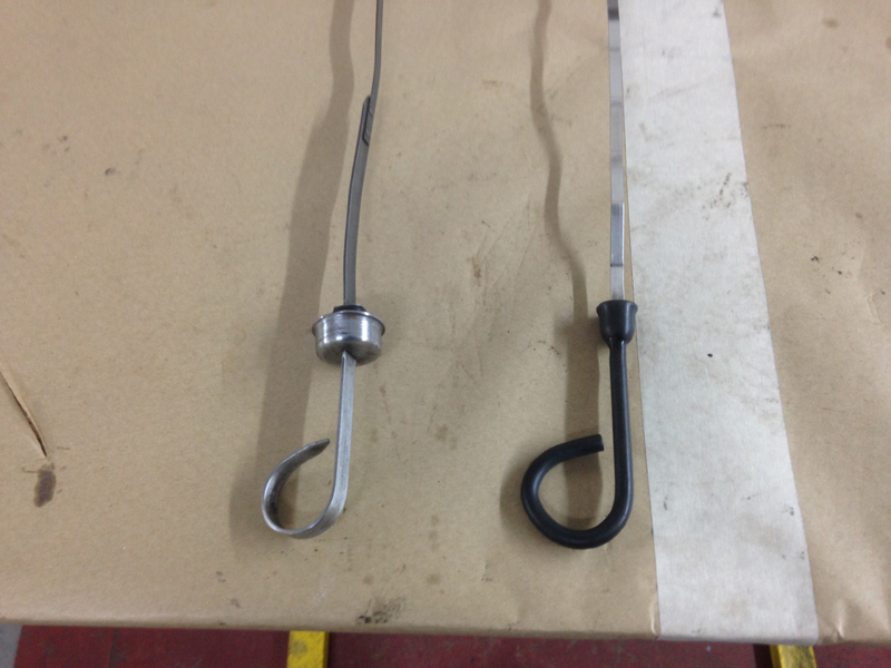
The engine dipstick is new so only needed a key up but the transmission dipstick needed a good clean up back to shiney clean metal:
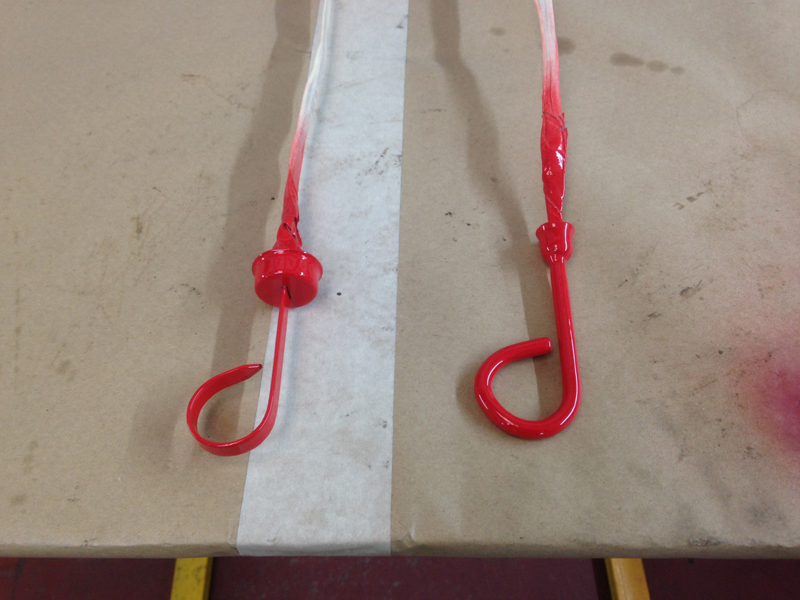
Then after masking up the sticks as cleaned the handles, painted them red:
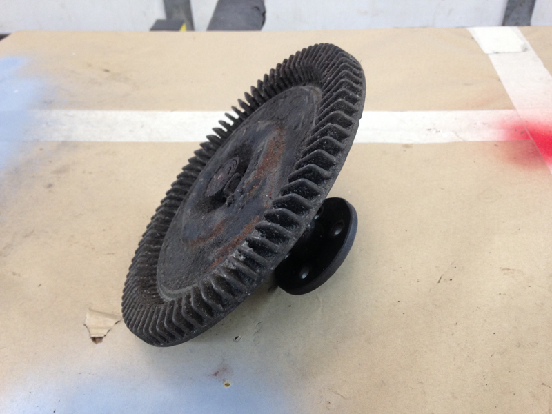
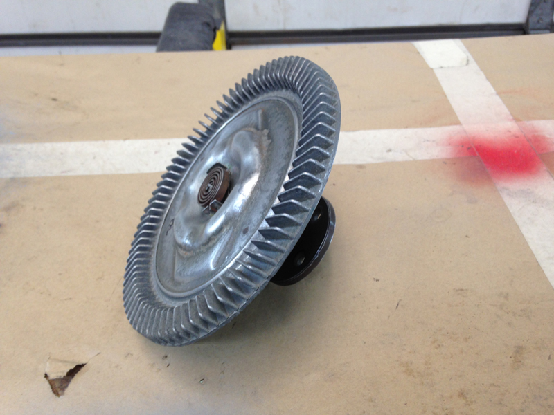
The cooling fan clutch was rusty and dirty so needed a clean up and re-paint before going back on the engine:
After cleaning and keying it up and getting all the surface rust off:
Then freshly painted satin black:
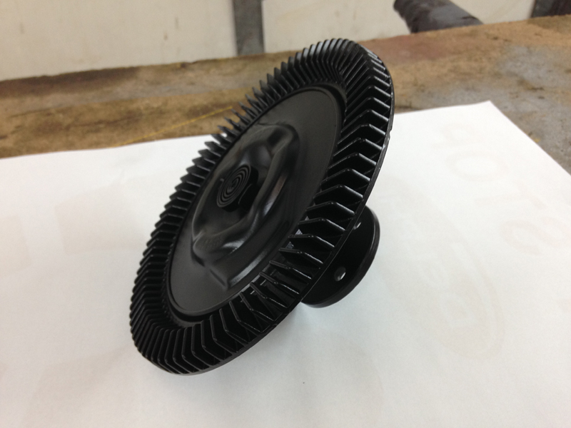
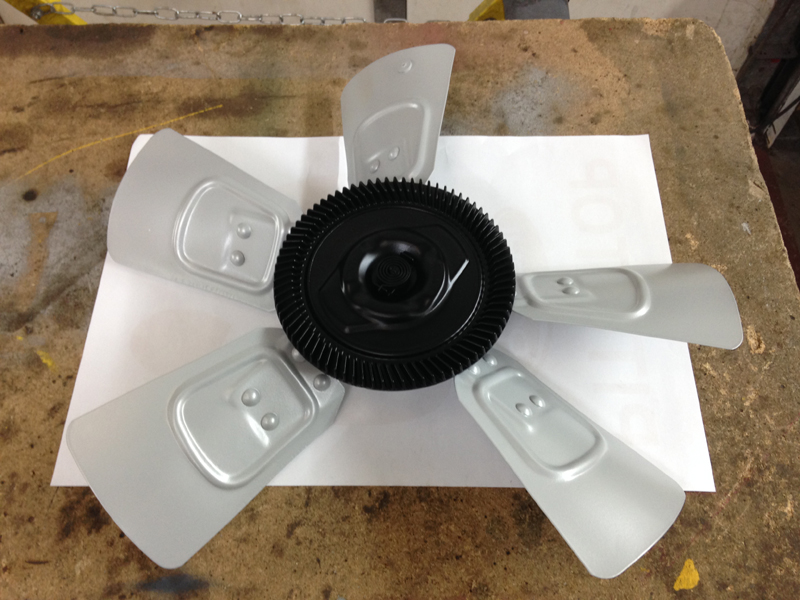
Then bolted back onto the freshly powder coated fan:
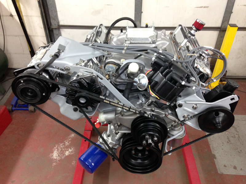
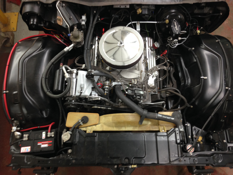
With the rest of the engine parts now in stock we could complete the engine, the intake manifold was installed along with the new carb spacer, HEI distributor unit, engine breather, new polished air conditioning pump, original alternator that was polished, all the brackets powder coated, new vacuum line fittings, new HT leads and holders:
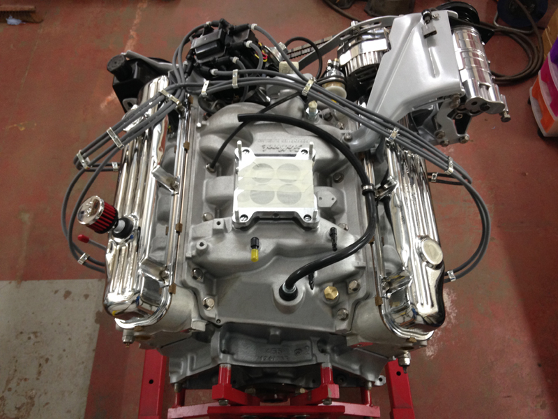
New drive belts, powder coated pulleys, new stage 1 fuel pump, new rubber hoses and lines, custom made fuel filter mounting bracket, new coolant bypass hose, new thermostat housing and thermostat and several other new parts:
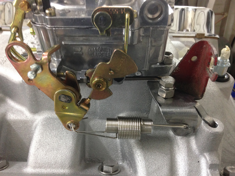
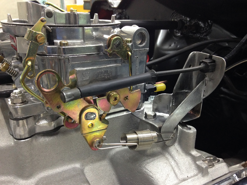
We installed the new carb and realised the new duel throttle return spring set up wouldn't connect with the original hole:
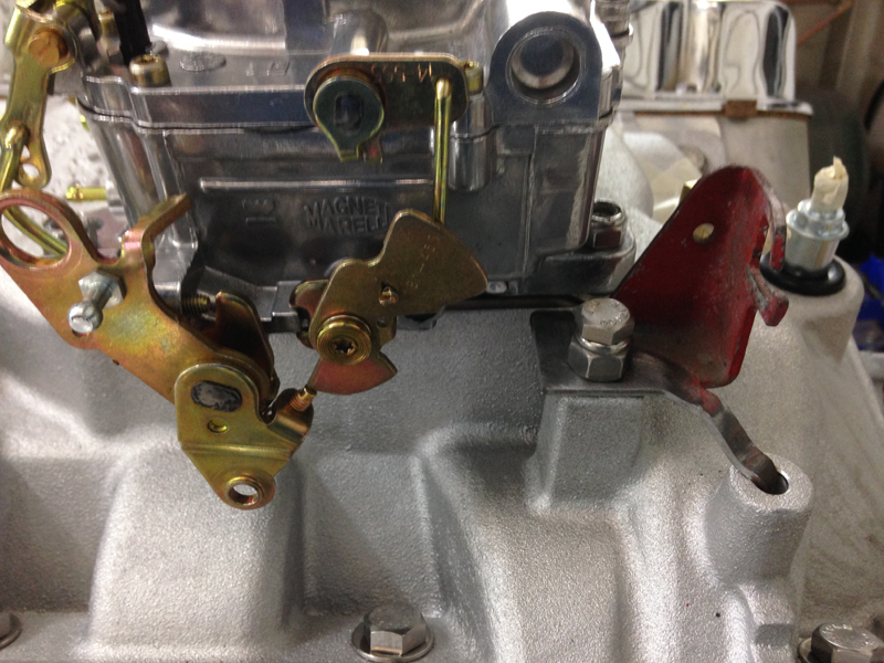
So modified the bracket a little:
The new air filter assembly uses a drop down base to maximise bonnet clearance, the problem with this is that it causes a few clearance issues itself with the carb. The first one being the fuel inlet:
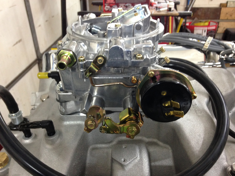
Edelbrock make a different fuel inlet pipe espicially for this problem, which we installed:
The second problem was the air filter housing base fouling on the electric choke housing in this spot:
The simplest solution was to reshape the base at the point that was touching:
Once we were happy with the fit of the base we had it powder coated silver to match the other engine parts while leaving the top chrome plated:
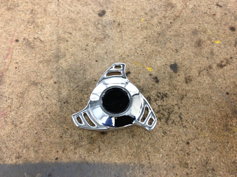
The new air filter wing nut of this type is available with various manufacturers badges in the centre of them, unfortunatly the Buick one is no longer available, so we chose a plain one:
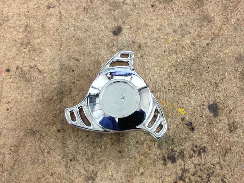
But felt it was a little bland so painted the centre of it black:
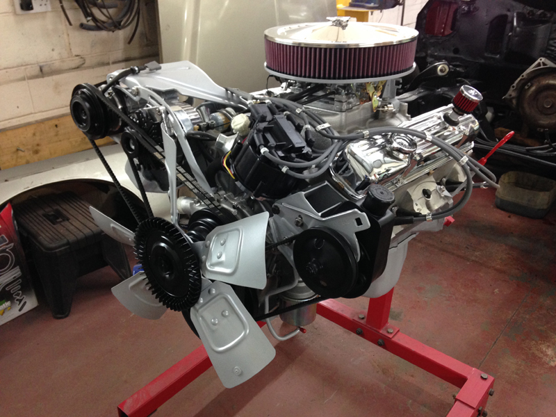
Then once it was installed the engine is complete and ready and waiting to be installed in the car:
Before installing the engine back in the car we gave the chassis and all the parts that could be seen from under the bonnet a good clean up and painted them satin black:
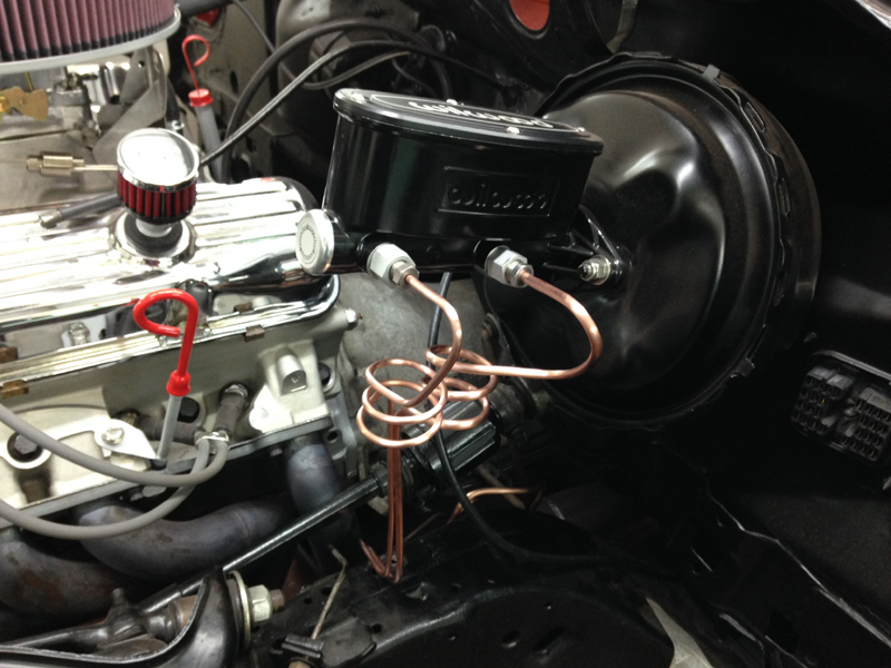
The master cylinder and servo assembly has seen better days, we have some upgraded front brakes for the car and a new Wilwood aluminium master cylinder, the servo was pretty good so we got a service kit for it to replace a few of the parts which commonly causes issues with age:
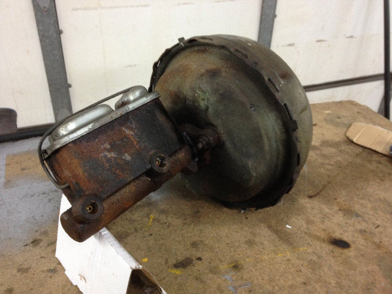
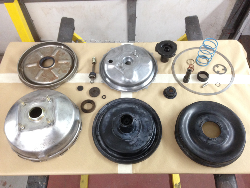
First job was to strip the servo down and clean up the housing and inspect all the parts:
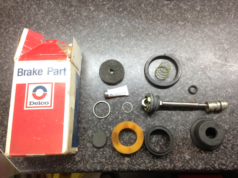
This is the service kit with the replacement parts:
All re-assembled and prepped for paint:
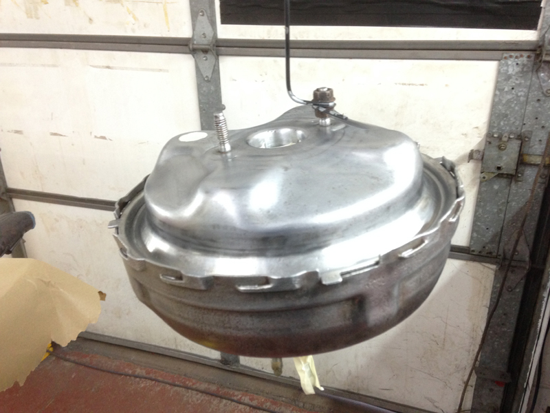
And finished in fresh satin black:
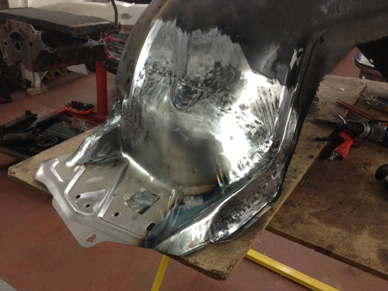
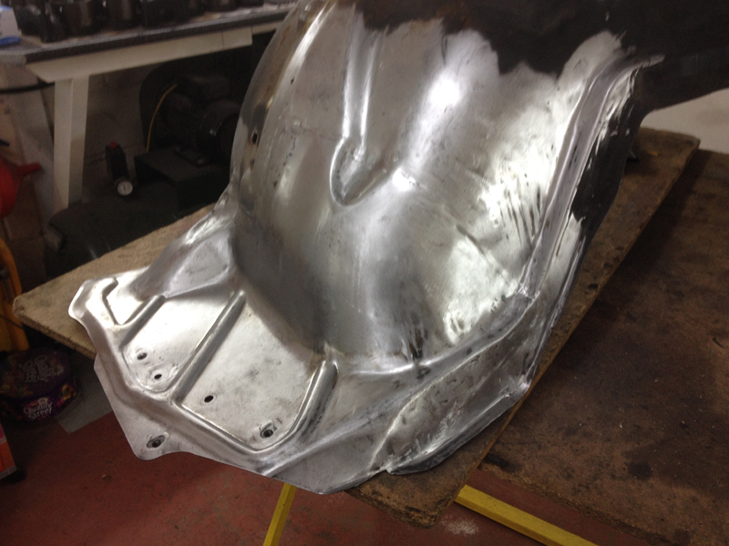
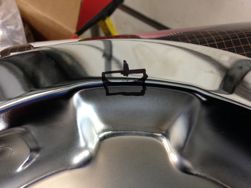
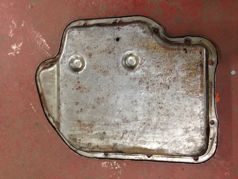
One thing we hate about these old cars along with most other workshops is the lack of an oil drain plug in the transmission sump. When the time comes for servicing and replacing the filter in the transmission you have to remove the sump, by doing this you have no choice but to remove the bolts for the sump and cover yourself and your floor in roughly 10 litres of transmission fluid. We like to install a drian plug in these sumps which makes things much easier in the future, not just for us, but for anyone carrying out transmission work on the car, the first step is deciding were the plug will be and marking the sump:
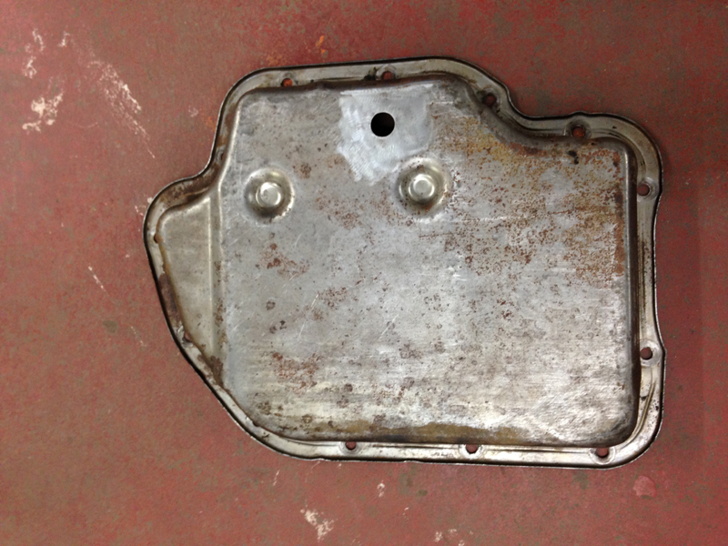
Step 2, drill the hole:
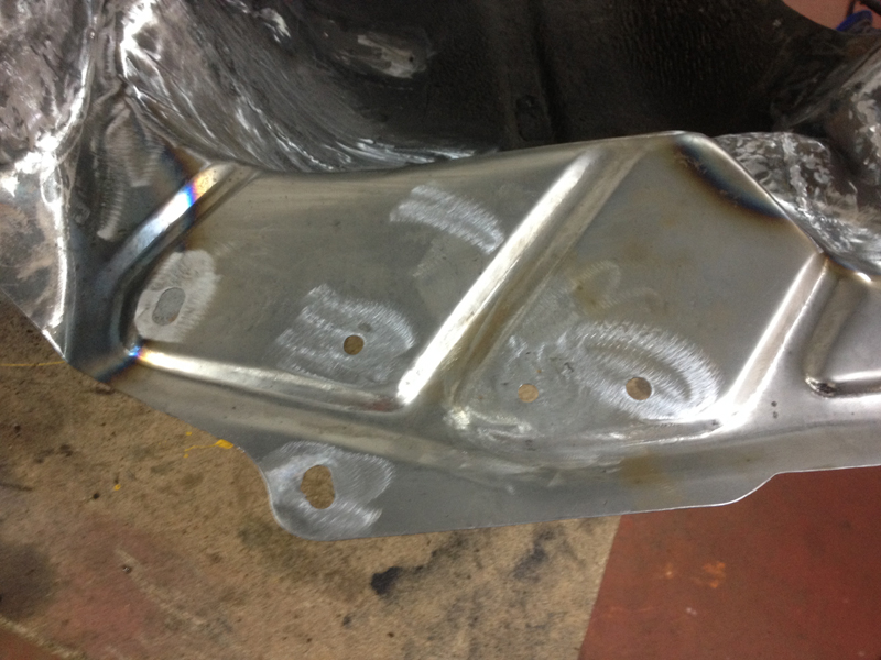
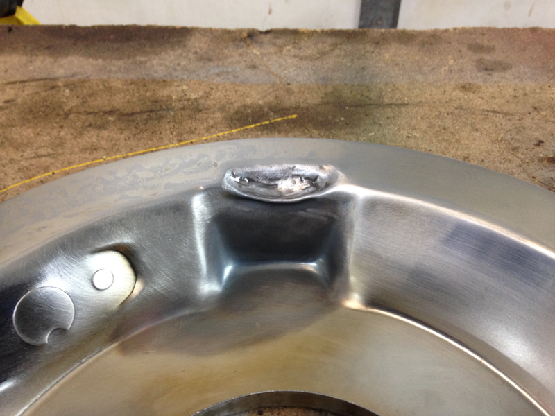
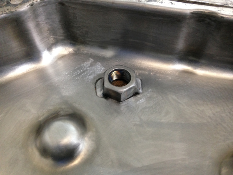
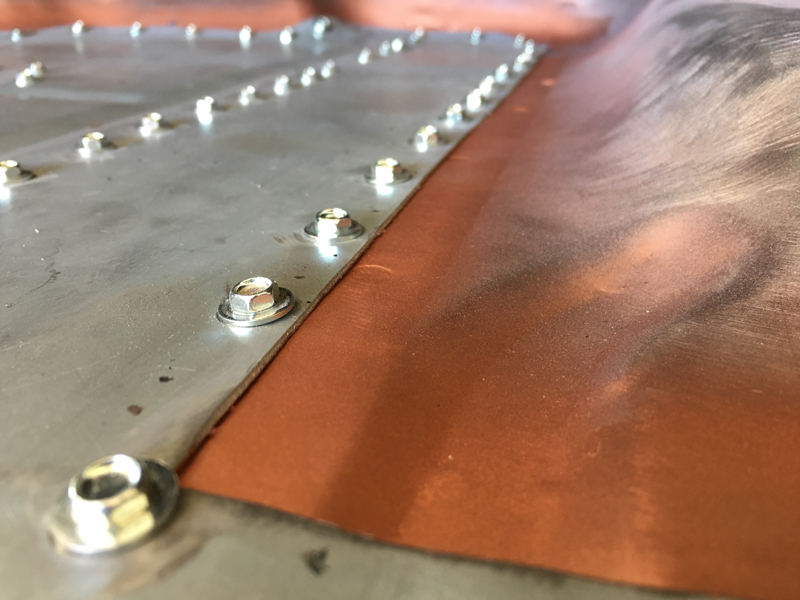
Step 3, weld a nut to the inside of the sump:
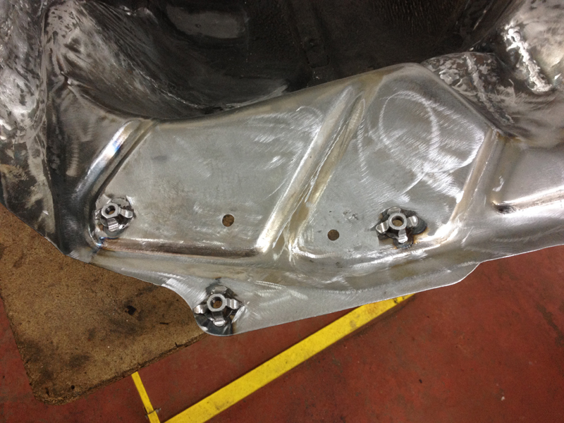
The final step, clean all the loose weld splatter off and the penetrating welds from the outside and install the drain plug. We will have the sump powder coated silver to match the engines sump pan:
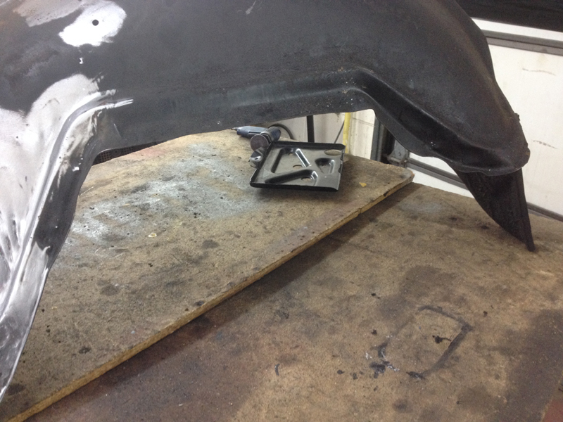
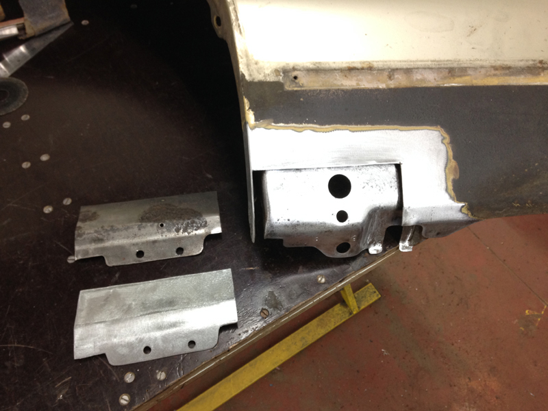
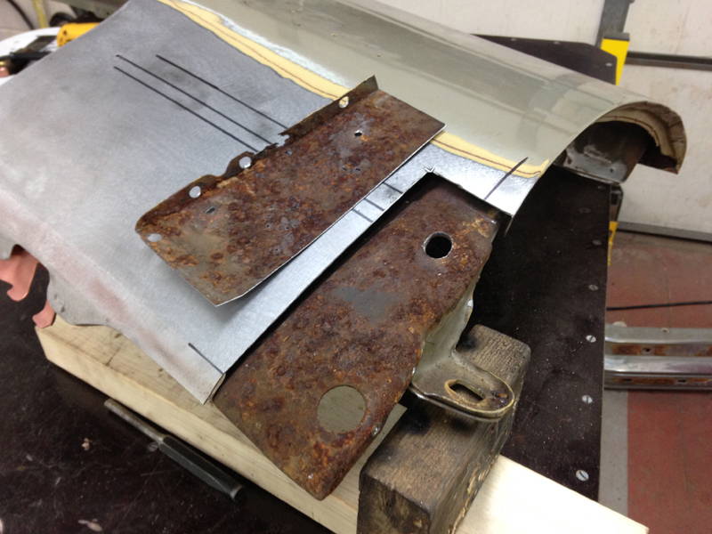
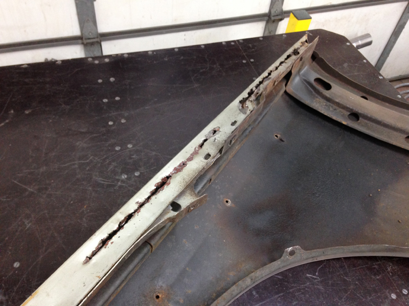
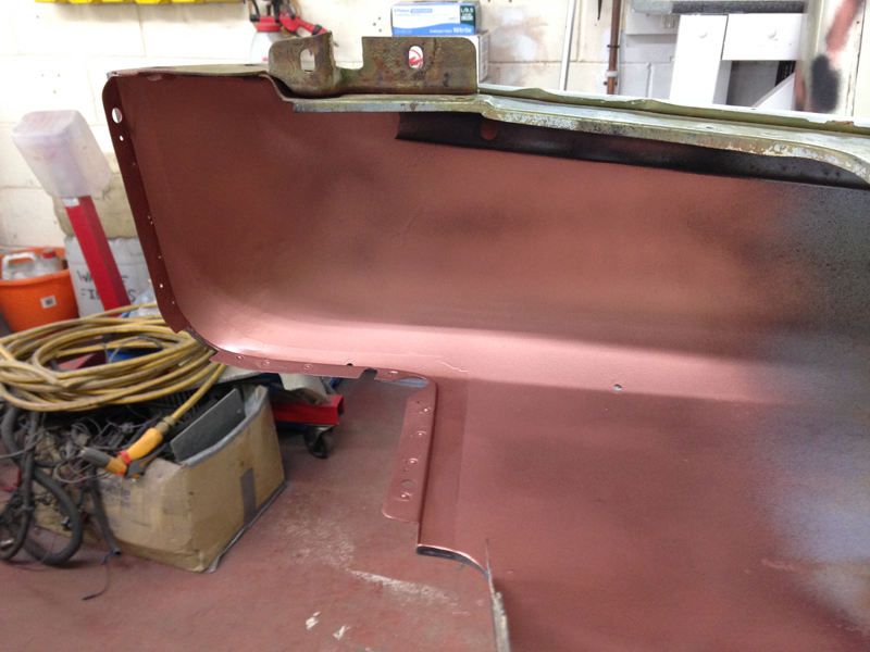
This inner section of the front wing on the passenger side of the car is removable from the factory but the driver's side is not. The owner of the car suggested we make it removable to match the passenger side and for making working in the engine bay easier and then we can have both removable pieces powder coated satin black to match eachother:
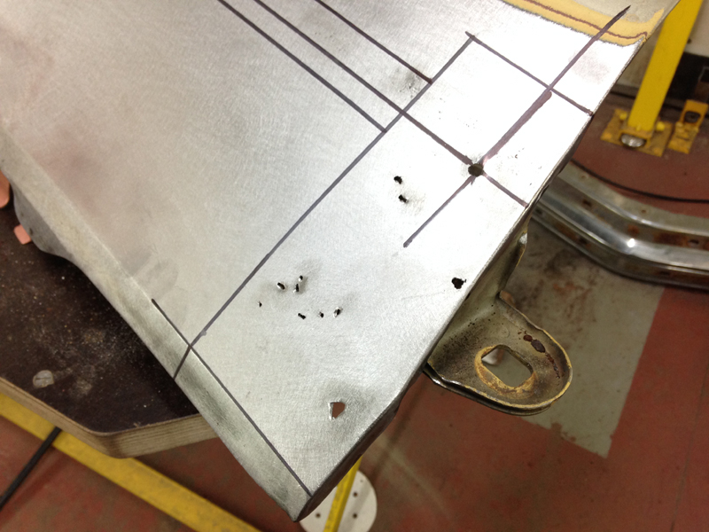
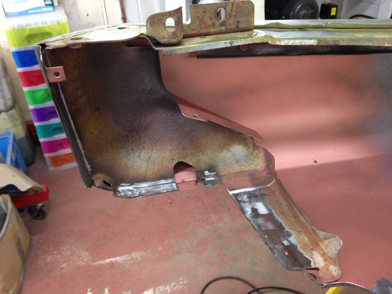
The first step is to make the 3 holes that the bolts will pass through and then drill out the spot welds and remove the inner piece:
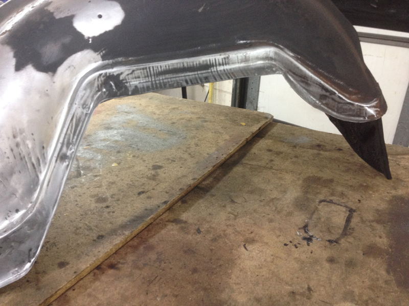
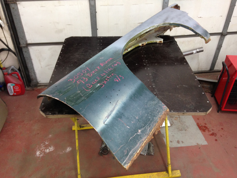
The inner piece removed from the wing:
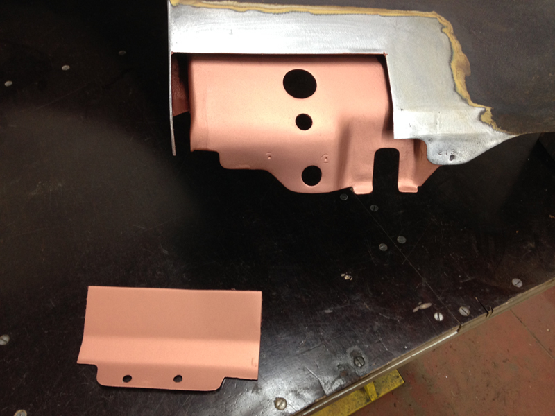
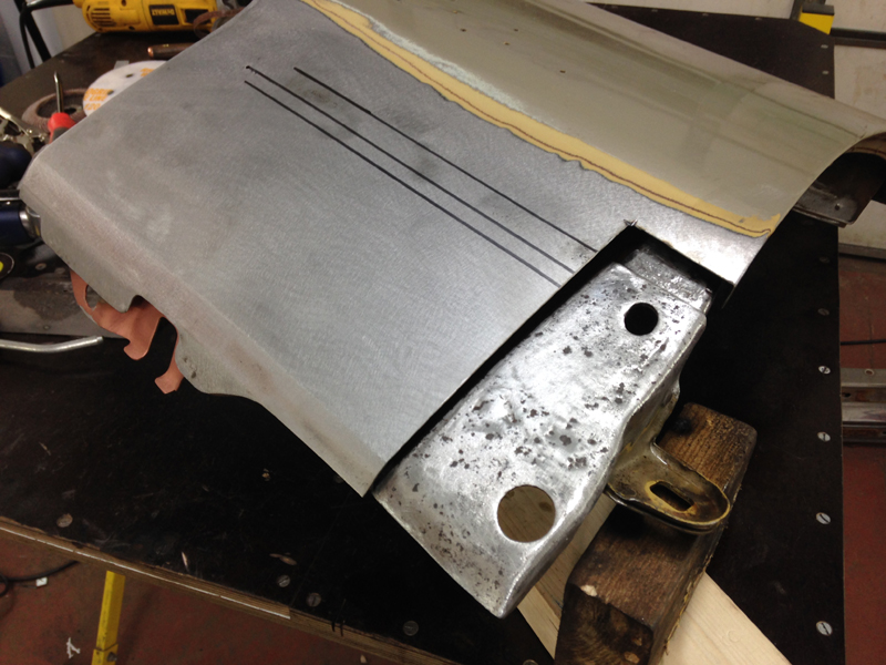
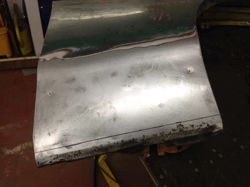
We welded up the original spot weld marks on the wing and tidied up the metal in general:
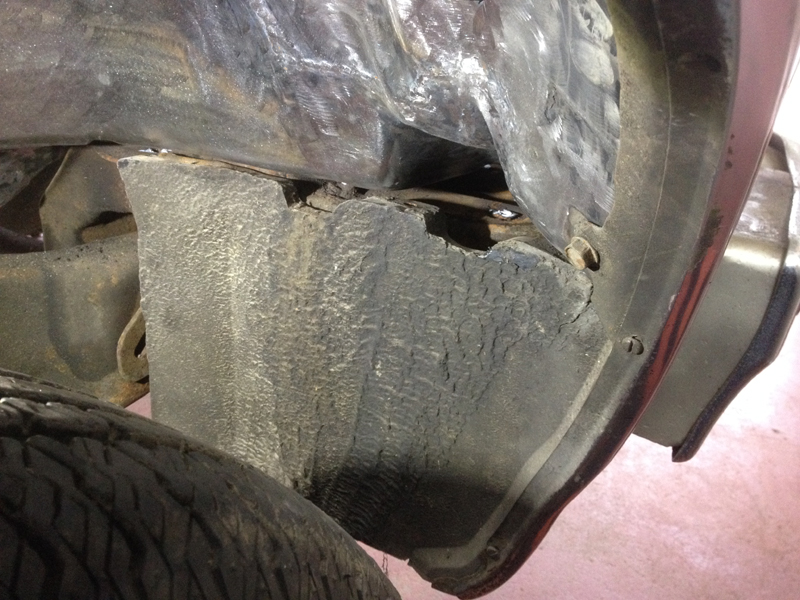
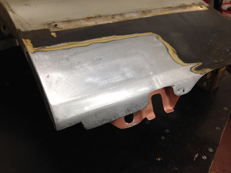
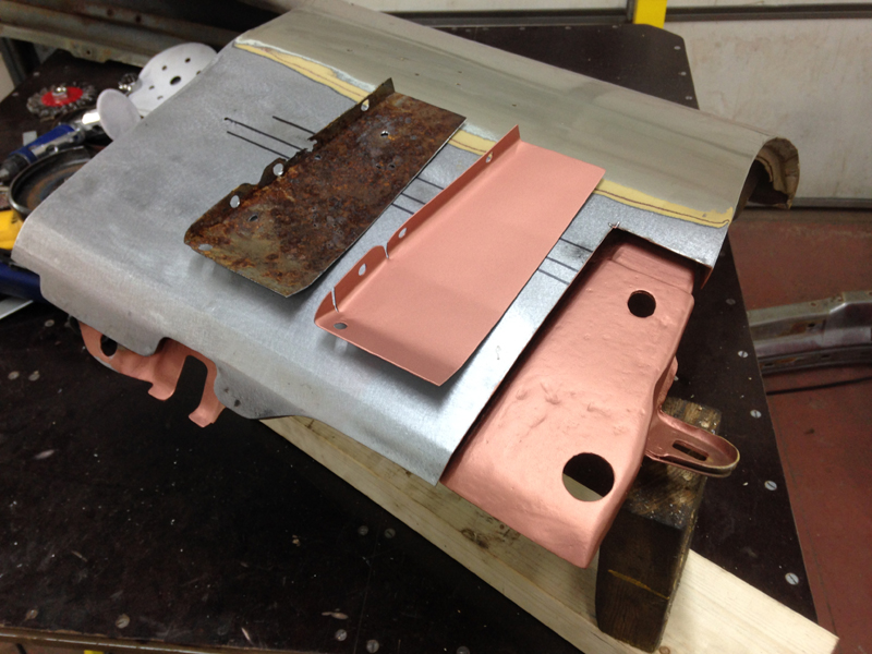
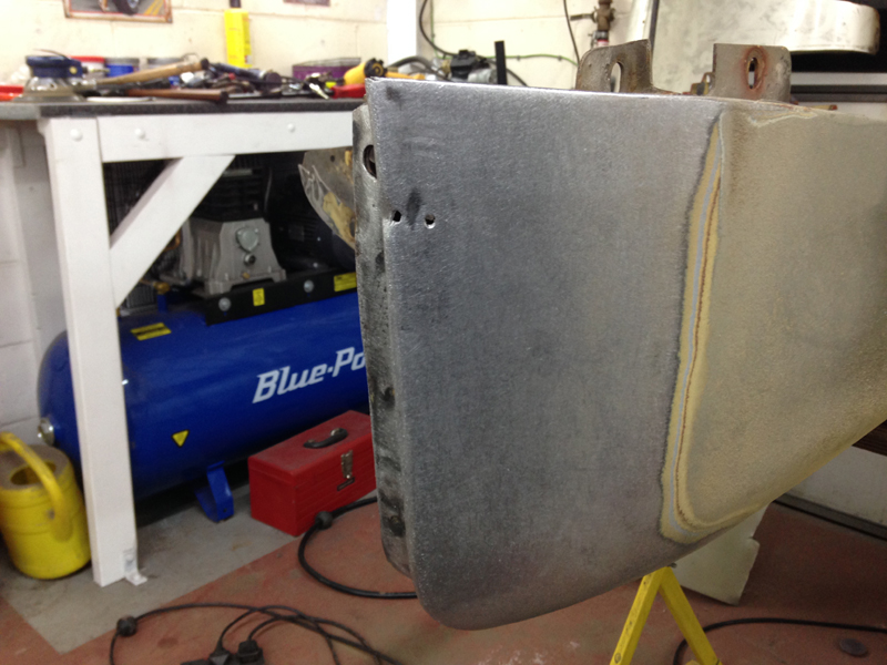
Then turned our attention to the removable piece:
Then carried out the same treatment on the removable piece that we did to the wing:
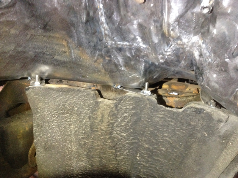
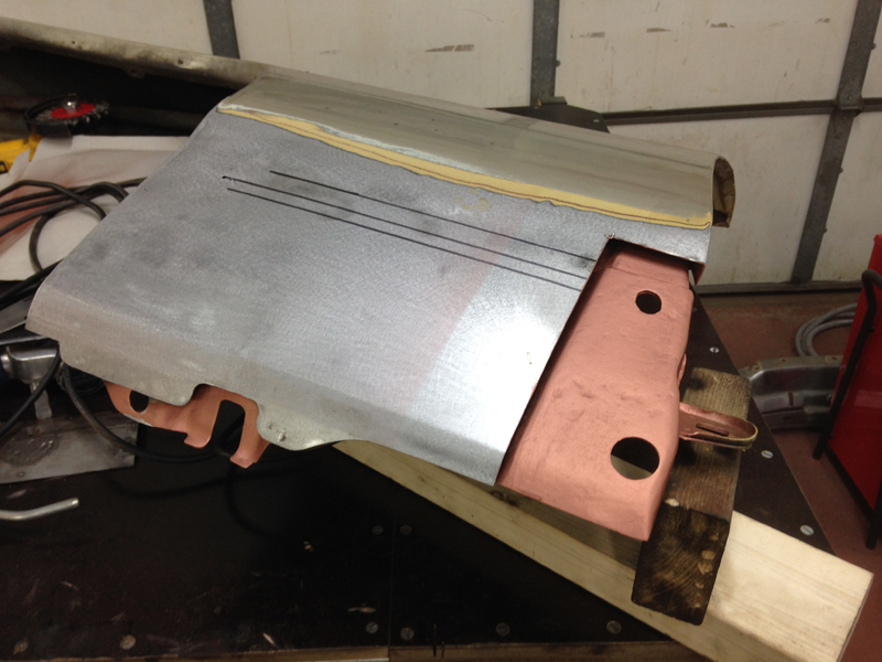
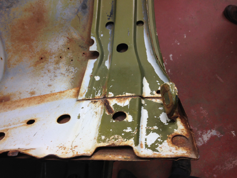
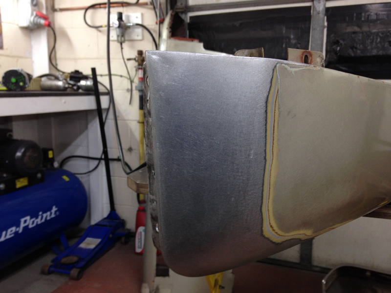
Then welded on some nuts to the rear of the wing:
This section is now removable in the exact same way as the passenger side one is:
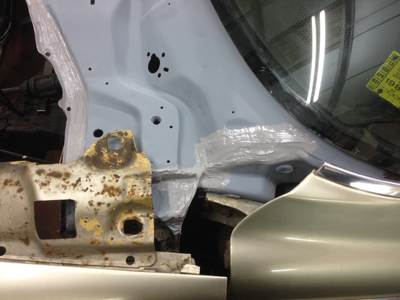
At this point the owner of the car decided that he wanted us to carry out a full bare metal respray on the car and tackle any rust issue we found, the first step was to remove the rest of the front panels so we could concentrate on getting the rest of the bulkhead and scuttle area painted so that the engine could be put back into the car. First up the drivers side door hinge area:
This side wasn't to bad, we found a couple of small holes:
Which we welded up:
The passenger side before clean up:
After cleaning up:
The bottom of the scuttle panel area was rusted out:
There was no point trying to patch this, the best thing to do to stop the rust spreading or coming back was to cut it out:
And make a new section from scratch:
Trial fitting the repair section:
We painted the rear with weld through primer so that the new section will be protected in the places you can't get to once its welded in:
The area on the car where the repair goes needed a good clean up and some pin holes welding up:
And then again coated with weld through primer:
The repair welded in place and the welds ground down:
We coated the entire inside of this area with a brush on anti-rust primer which will keep this area clean and solid for years to come:
Then we removed both of the doors, cleaned of the paint around the door hinge mounting points and primed both sides:
And the passenger side:
The repair on the passenger side in primer:
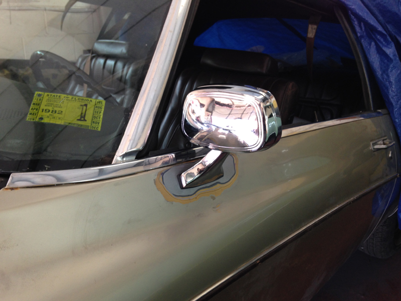
Whilst the primer was drying we decided to have a quick look at something else. The car originaly only came with a drivers door mirror only. The owner of the car had requested we fit a passenger mirror. After a long search it seems that either Buick never made the Riviera with 2 door mirrors or that the passenger mirror option wasn't very popular. After some more searching we discovered that the door mirrors from mid 80's Oldsmobiles matched the original Riviera one exactly and was also availble in electric mirrors. The owner of the car liked the sound of this option, so we ordered the mirrors. The only question now was how to opperate them. We done some more searching and found that the door mirror switch from an 80's Jeep Grand Wagoneer matched the style of the rest of the Buicks door switches. So after hunting down a switch we got to work on making it fit the car. Here is the stock drivers door switch housing:
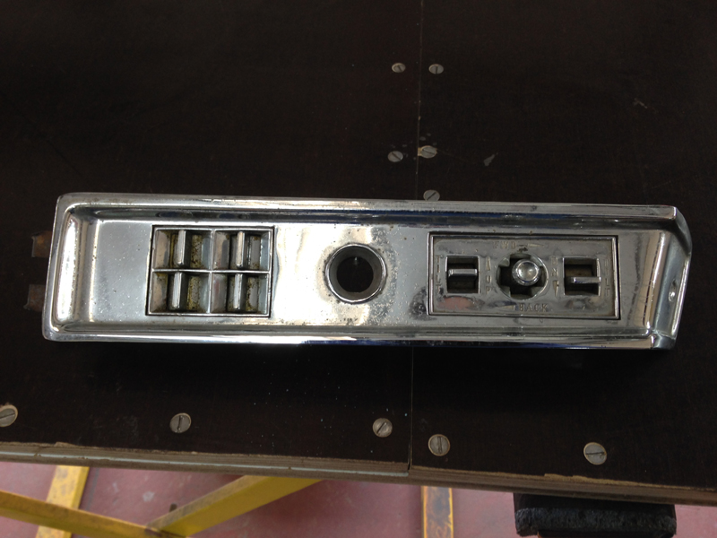
And with the new switch. The original driver's mirror was controled by a knob which moves cables to move the glass. We had to cut this section out and make a new hole for the switch to sit in:
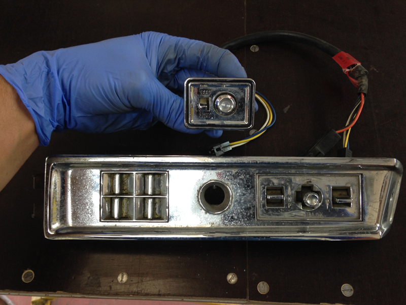
Here is the switch fitted into the housing. We will be getting the main housing re-chromed as its very pitted:
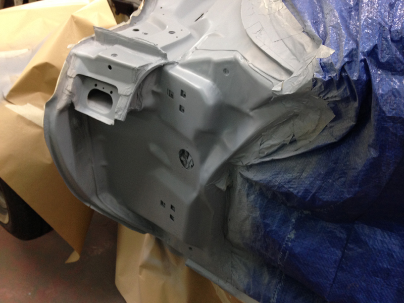
With the primer now dry on the bulkhead and scuttle panel, we could continue with this. First step was to key up the rest of the paint and apply new seam sealer over all the factory joins:
And then repaint the entire section satin black:
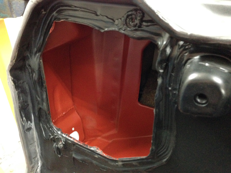
The inside of the scuttle panel had lots of surface rust were the paint had peeled away over the years. Cars of this era tended not to paint areas like this from the factory and if they did they left in a red oxide primer. We cleaned the whole area up and gave it a good key up:
And then painted it with a red rust resistant primer for the factory look that should keep is from rusting for years to come. Once the paintwork on the rest of the car is done we will also waxoyl this area for further rust prevention:
Moving back onto the doors, we discovered that the new mirrors, whilst on the outside looked the same as the factory one, had a different fittment pattern to the original:
So we had to weld up the holes we wouldn't need:
Then measure for the new holes and drill them:
Now the mirror fits:
We then made a template of the drivers door and transfered it onto the passenger door so that the mirror on the passenger side would be in the exact same spot on the door as it is on the the drivers side:
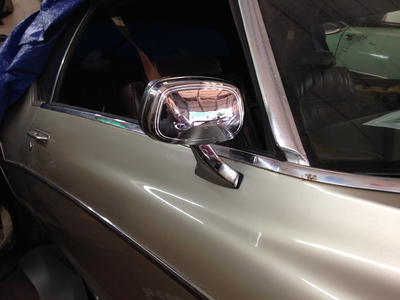
We now have a 73 Riviera with electric mirrors on both doors that have the same factory appearance as the original mirror on the drivers door:

Before we could put the engine back in the car there was one last job we wanted to finish. When we removed the engine out of the car, one of the transmission cooler lines fitting was siezed onto the pipe and snapped off trying to remove it, also both pipes were bent about and one had a previous repair join in it:
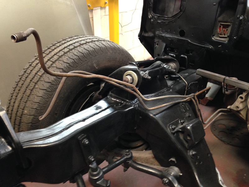
So we decided to just replace both pipes and fabricate new ones:
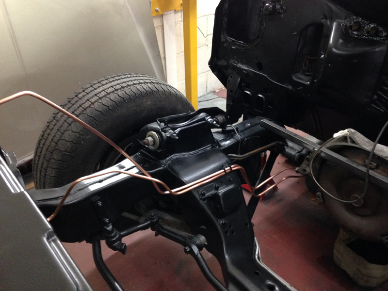
With that taken care of, we removed the new pipes and put them to one side then dropped the engine back in the car and started connecting things back up. The coolant, fuel, power steering and vacuum lines will all be replaced with fresh rubber as all the orignal stuff is perished and splitting open:
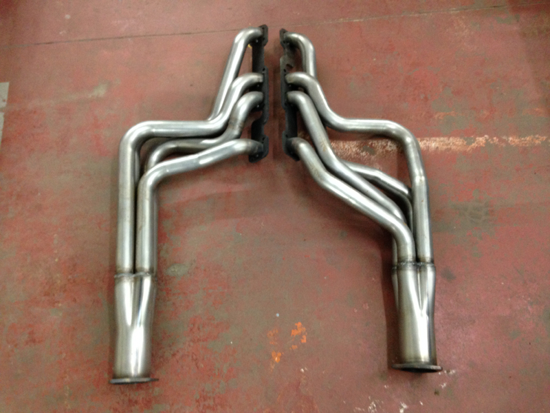
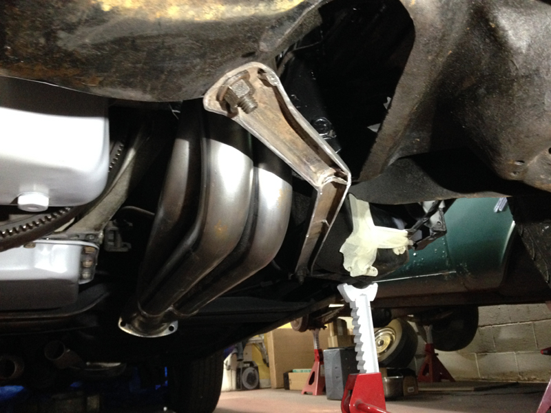
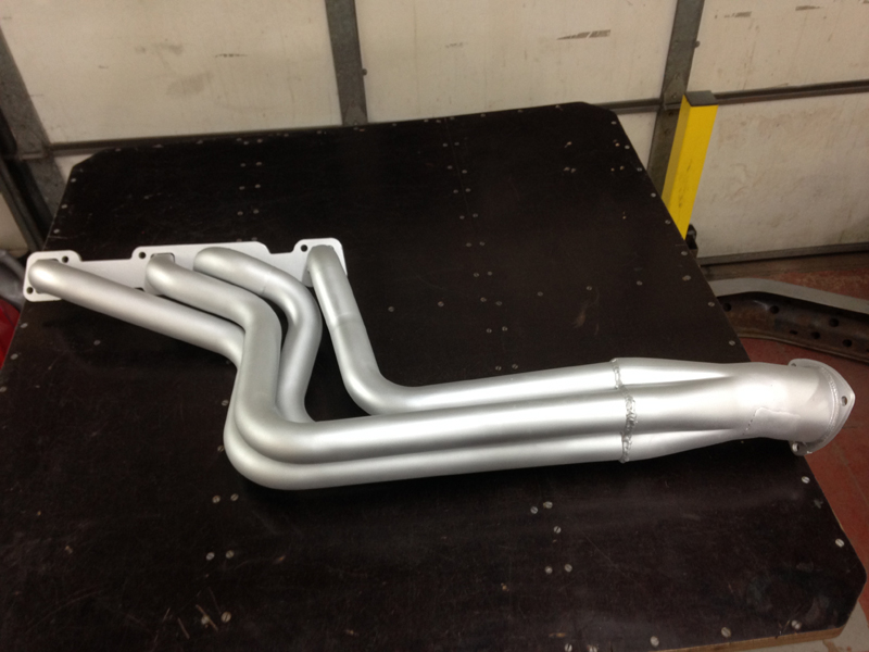
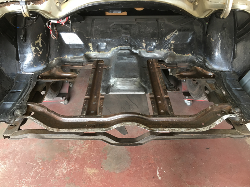
Keeping with the performance theme we ditched the original heavy restricting exhaust manifolds in favour of a set of steel tubular headers:
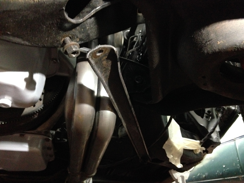
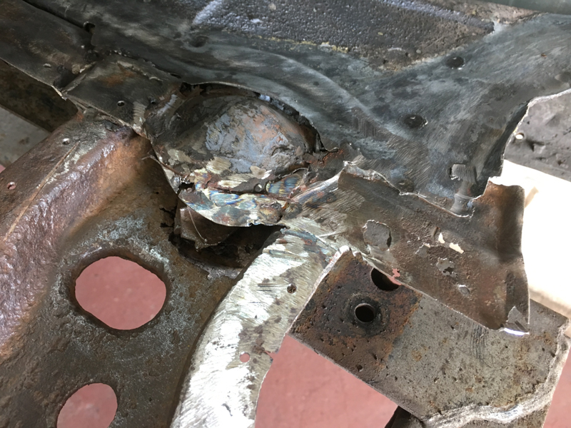
From past experience on all cars, 90% of the time after market headers never fit the car straight out the box, so we wasn't suprised that this car was no exception. Both sides were hitting the fuel lines and the subframe support braces, this is the drivers side brace:
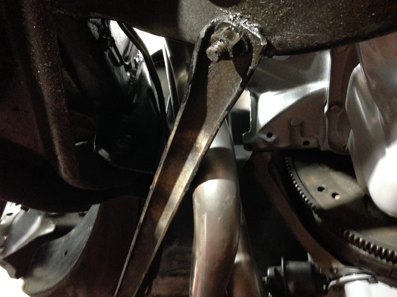
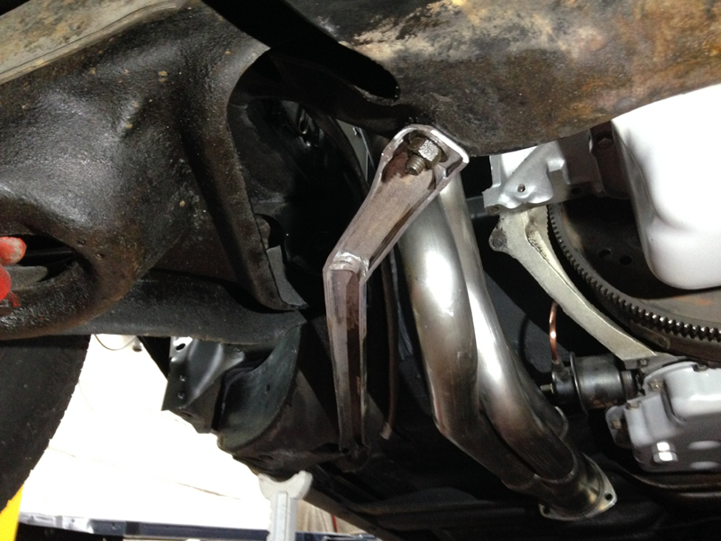
The passenger side did manage to fit just about but was touching the brace:
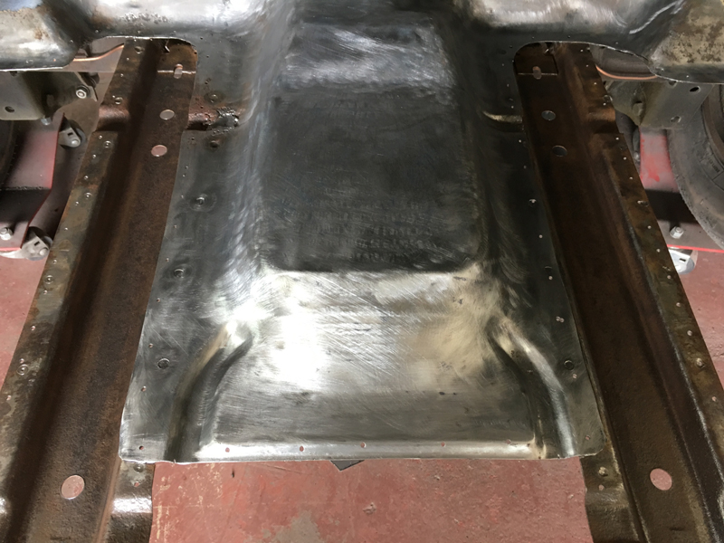
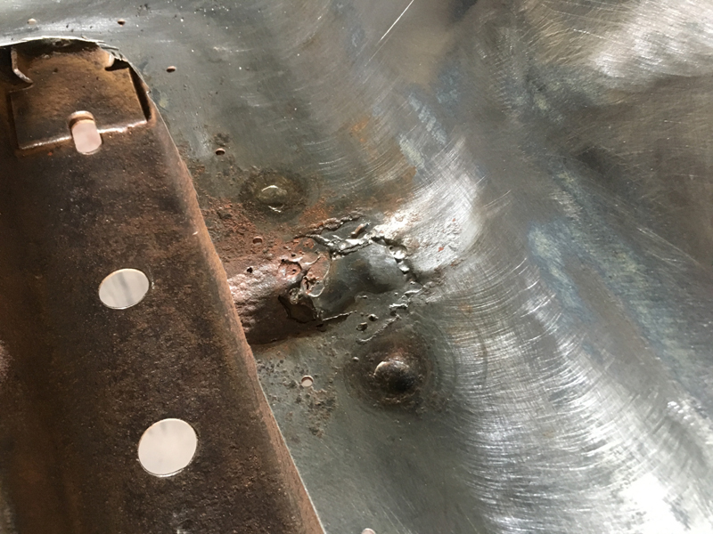
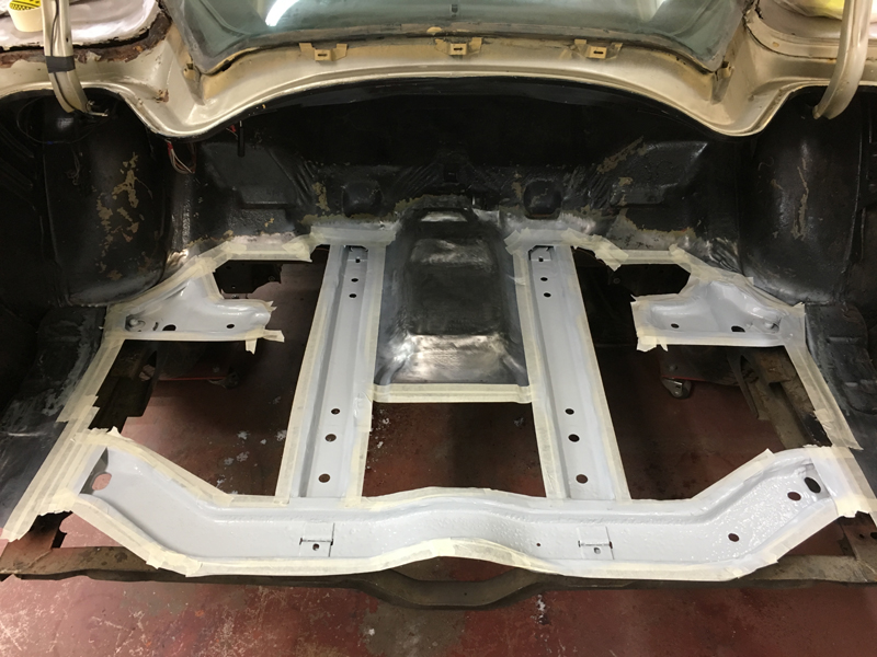
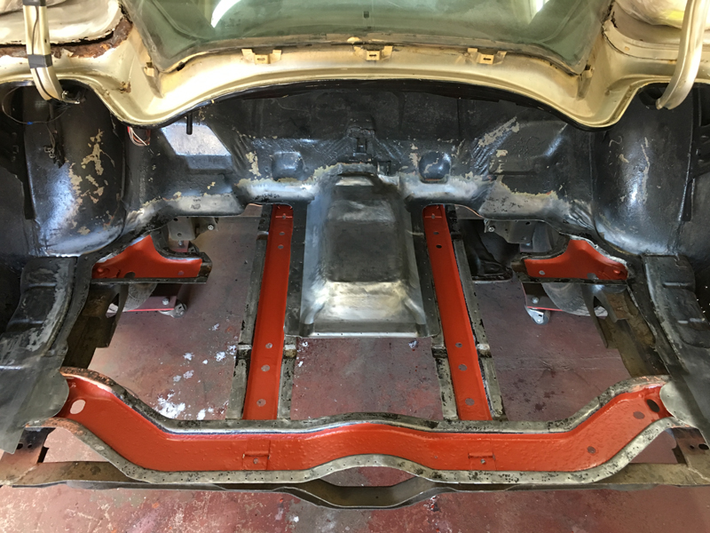
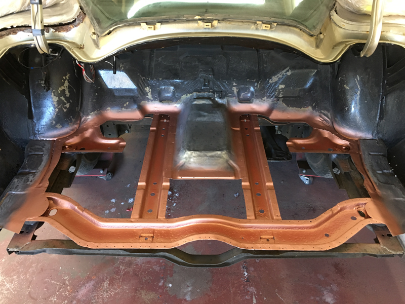
So we decided to modify both braces by cutting them and extending them and reshaping them. We ground the tops of the welds on top of the bracing smooth and shapped the metal nice as it can be seen from the above the engine bay but decided to only dress the welds a little from the under side to keep as much strength there as possible as the chassis will flex quite a bit when cornering. We will have both braces powder coated satin black for a factory appearance, the drivers side:
And passenger side:
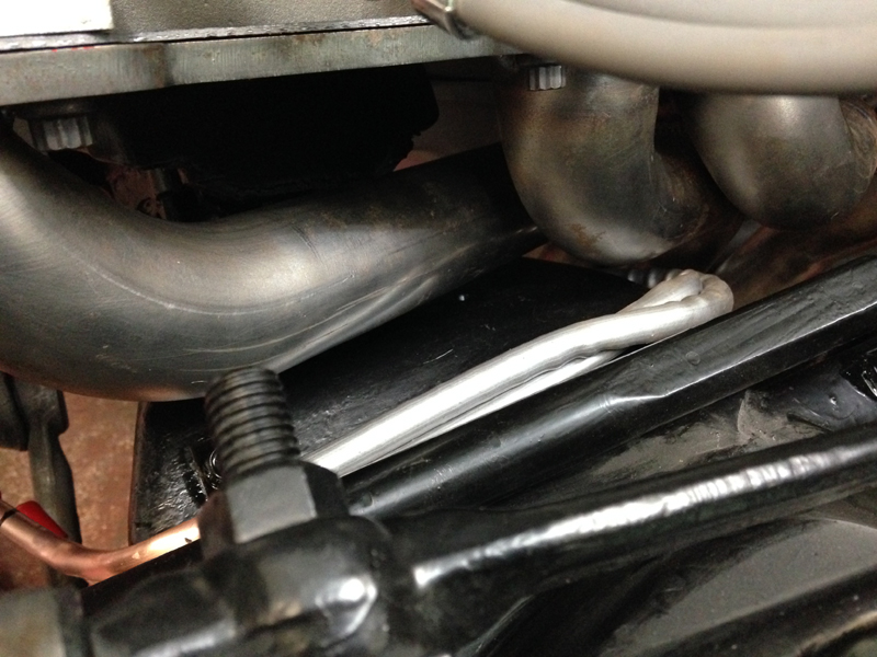
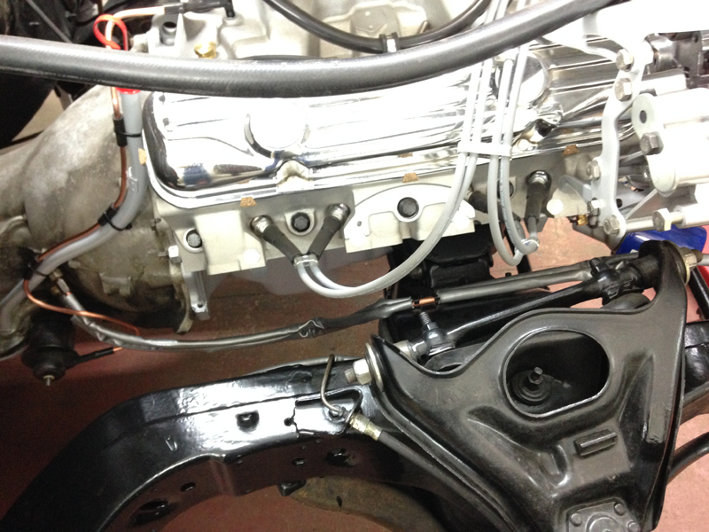
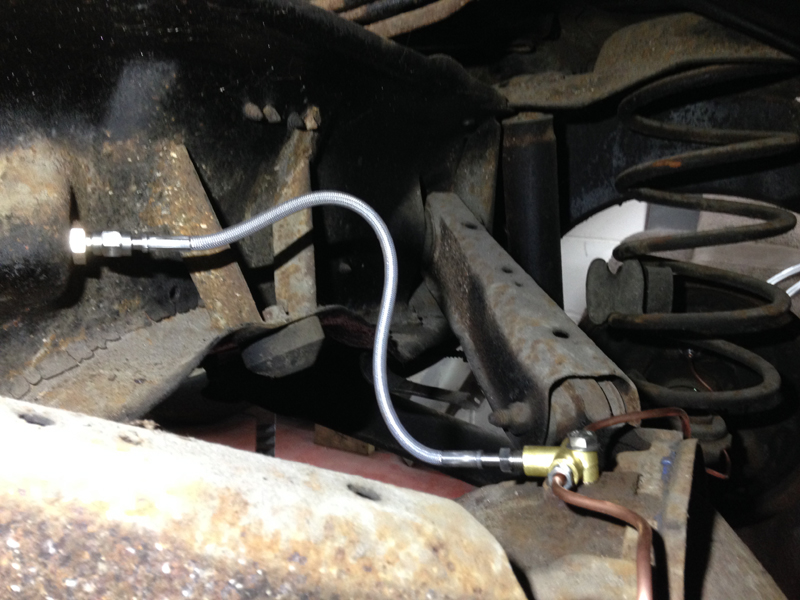
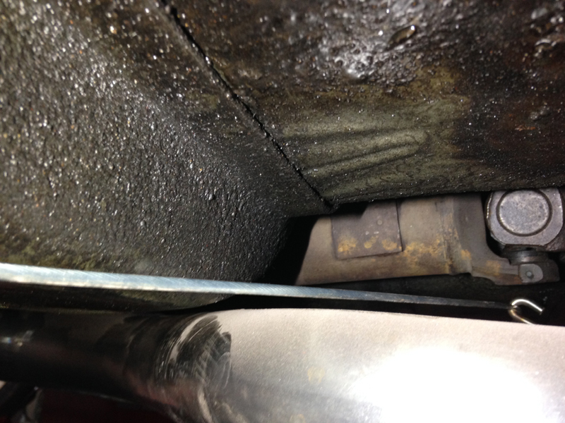
Now that both headers are actualy in the car we could worry about the fuel lines. The passenger side was simple enough, we just re-shaped the lines closer to the chassis and gave enough clearance but the driver's side had no room to move anything about:
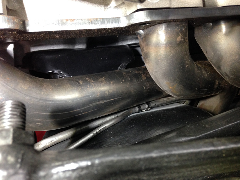
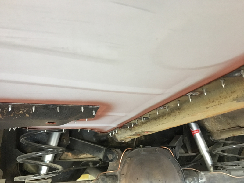
Our solution was to remove the header cut both fuel lines under the engines oil pan in the middle of the subframe, flare and end on the original fuel lines for a rubber join and make a complete new section from here up to the pump, this is the final outcome:
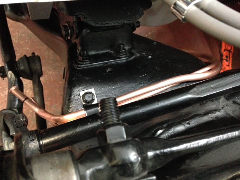
To finish the new lines off we fitted a protective heat shield over the line which will reflect the heat from the exhaust away from the fuel lines. The photo isn't very but the is loads of clearance between the exhaust and fuel line where fuel lines bend to go down the subframe. We also plan to have the headers ceramic coated once the engine has been run in, to help lower engine bay temperatures and so that the headers have a nicer look to them:
Another fitment issue was the throttle cable, anyone who has read this whole page may remember that we already modified the throttle cable bracket once for the return springs, we also said it would need further modification once the engine was in the car so that the cable opperates smoothly, the problem with the stock location on the new carb set up was that the cable was hitting the throttle arm whilst in opperation:
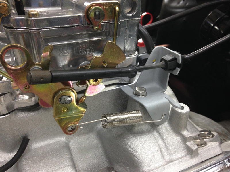
So with some further modification to the bracket we were able to relocate were the cable mounts onto the bracket and change the angle it opperates at, thus clearing the throttle arm on the carburettor:
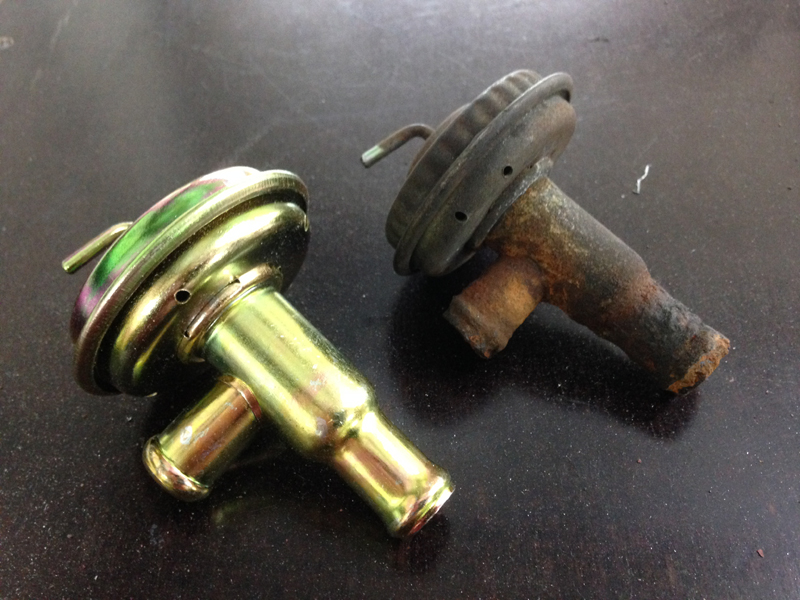
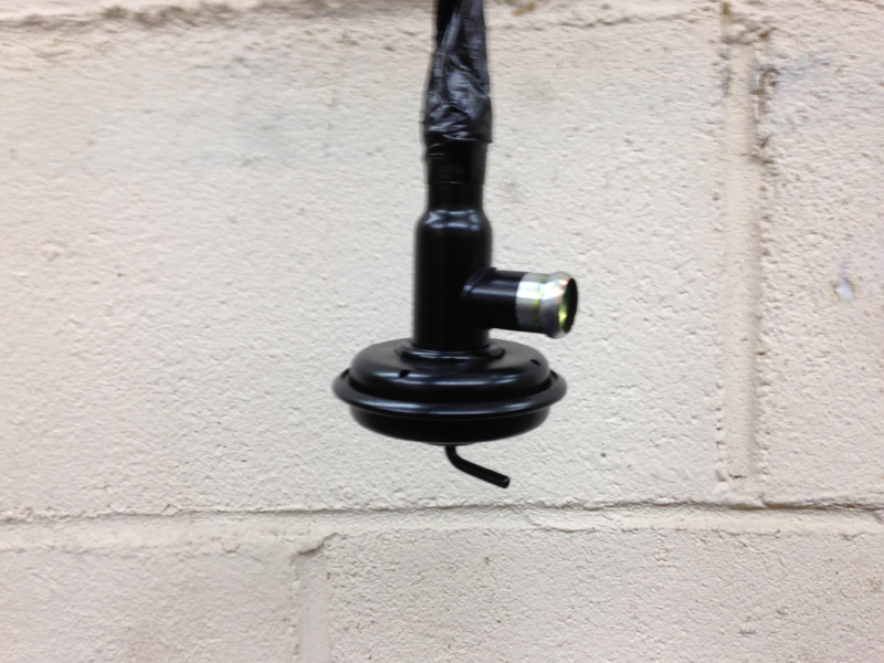
The original heater control valve was rusted up and sized solid and no use to anyone so we sourced a replacement which we will paint black:
The original starter motor works fine but was dirty and rusty:
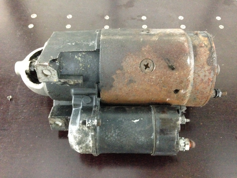
So we gave it a good clean up:
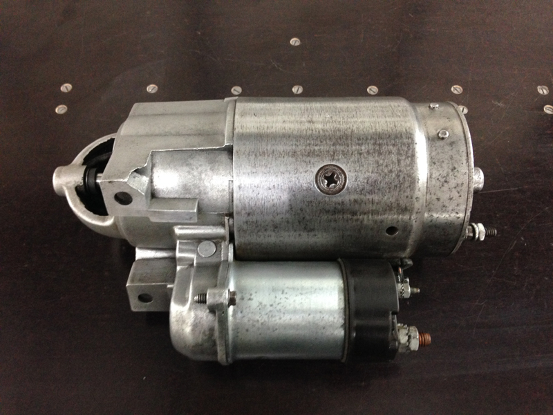
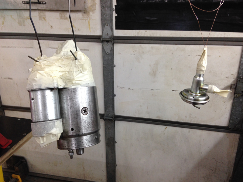
And got it ready along with the new heater control valve to paint satin black:
The painted starter motor:
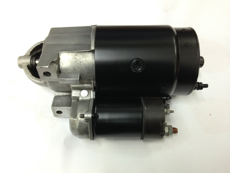
And the heater control valve:
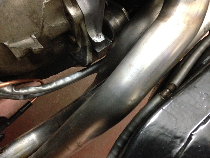
We also installed the heat shield sleeving on the fuel lines on the passenger side and the transmission cooler lines:
Because they run very close to the exhaust manifold. Again the photo doesn't show it very well but there is ample clearance between the exhaust and the fluid pipes but still worth having the heat protection around them:
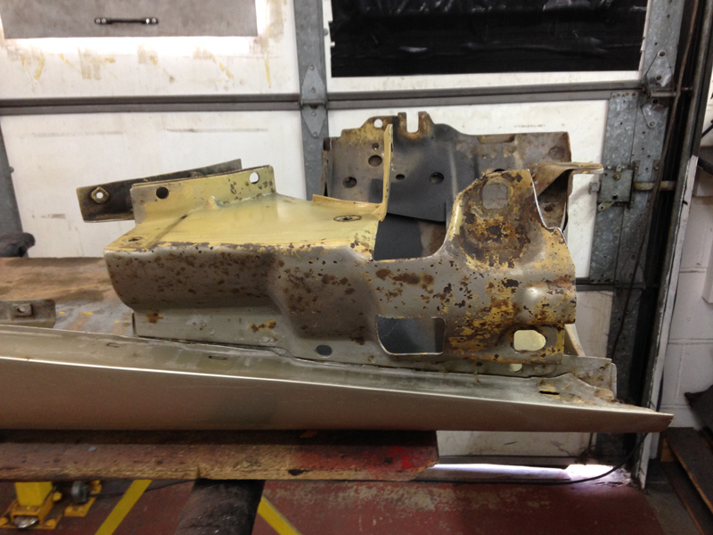
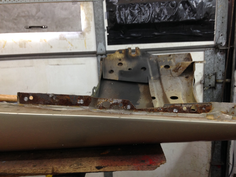
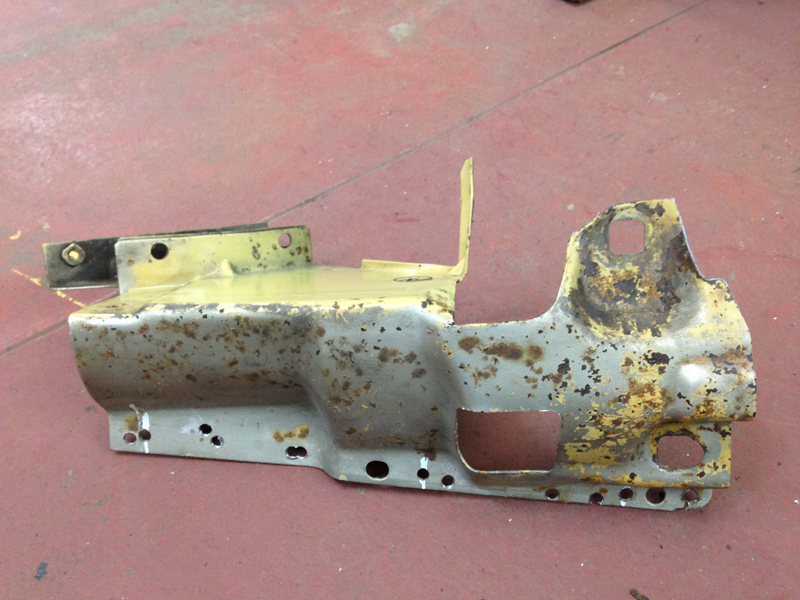
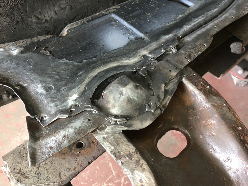
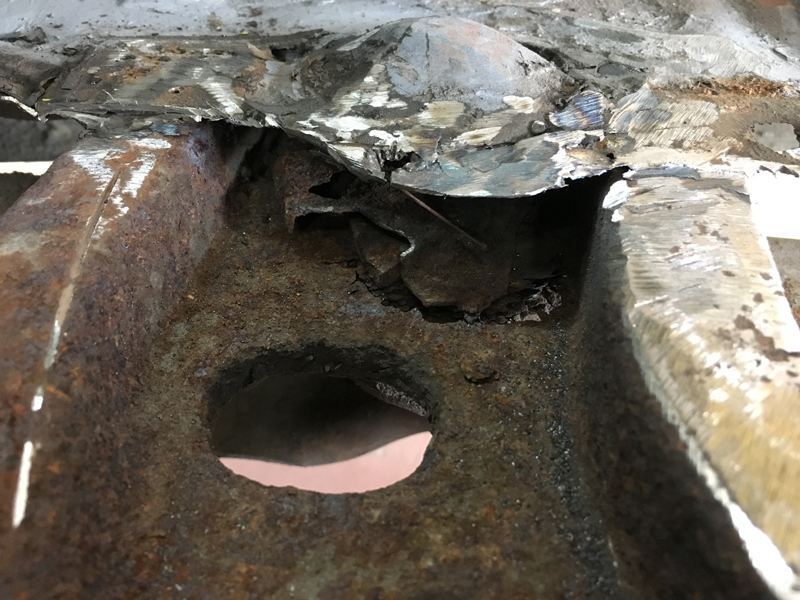
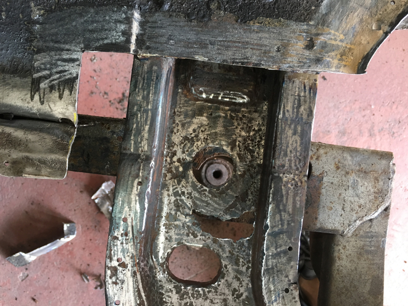
Next we wanted to install the radiator but had to address something first. We noticed this problem when the car came in but couldn't do much about it at the time, now that we have the entire front of the car removed we could address it. The car has shown several signs of an impact on the passenger front corner, the bumper is bent and dented, the passenger wing and front header panel are from another car and the chassis and bumper iron are bent, so much so infact that who ever repaired the car after its accident was only able to install 2 of the 4 mounting bolts for the bumper iron on this side:
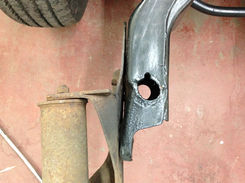
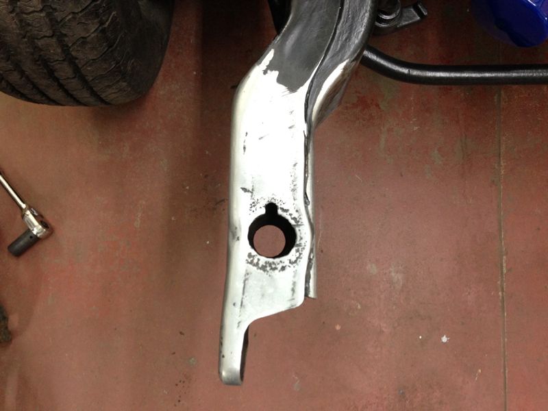
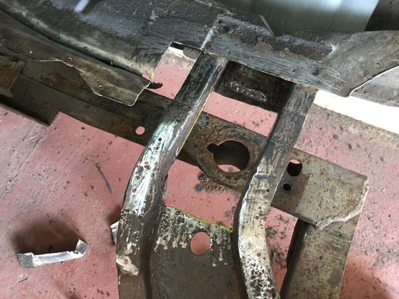
So we removed the bumper iron, stripped back the paint around the damaged area and cleaned up the rust and then set to work on straightening it out:
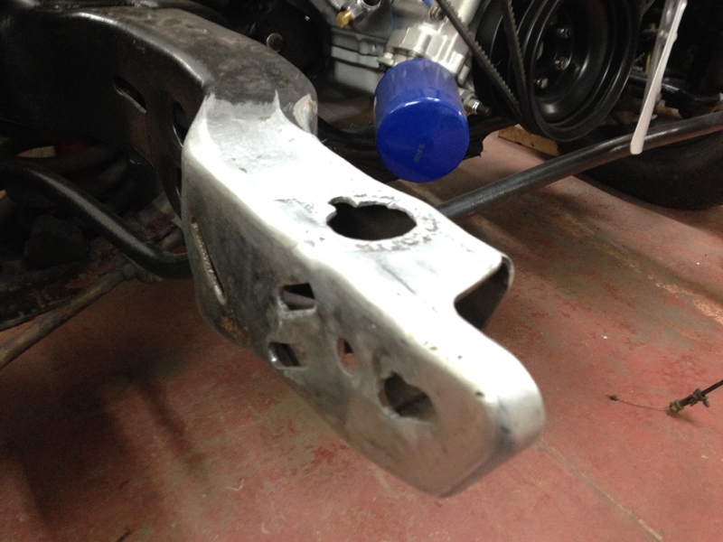
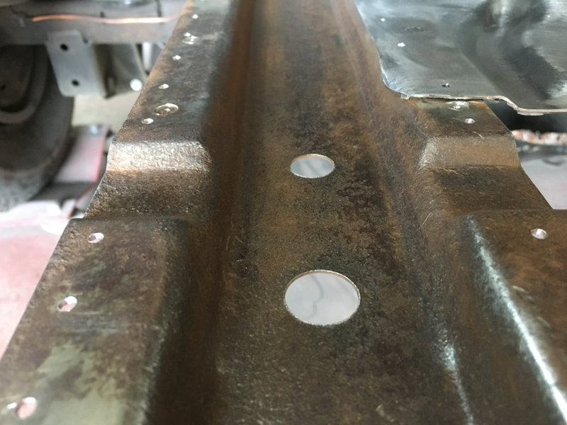
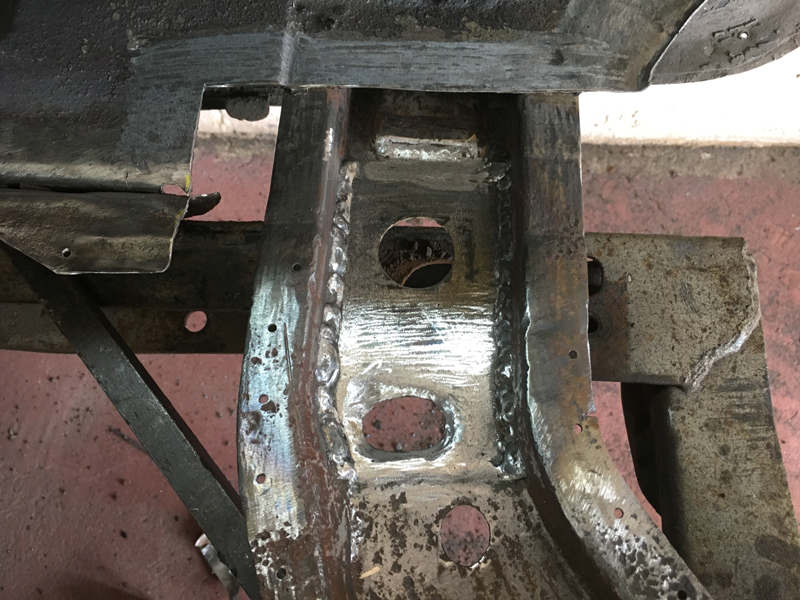
The final result isn't 100% perfect but all 4 bolts will now install, the bumper iron will sit flat agains't the chassis and the round hole on top that the radiator support panel bushes sit in is now the correct shape again:
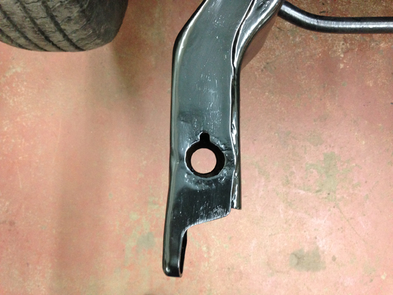
After the repair we touched up the paint on the area:
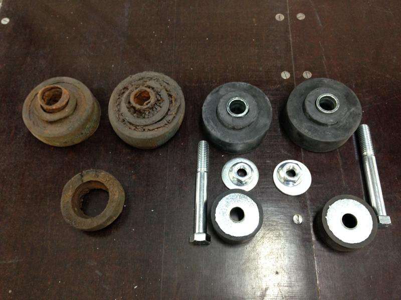
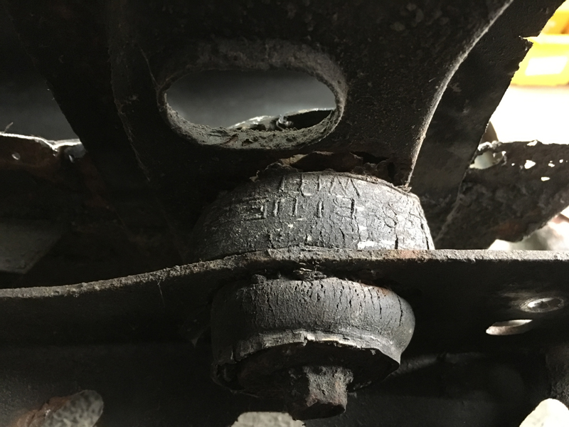
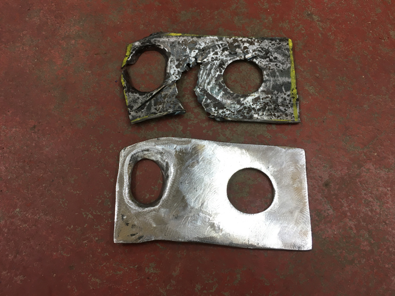
We got new radiator support panel bushes too, the ones on the left are what was on the car, 1 of the 4 was missing and what was left of the other 3 was scrap, the ones on the right are the replacements:
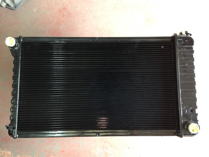
Because of all the dirt in the coolant passages we found inside the engine and tell tale signs of leaking on the radiator itself, we sent it away for testing:
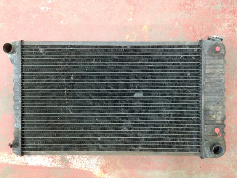
The outcome was that it was infact not holding pressure and blocked. We had a specialist radiator company rebuild the original radiator using a 40% more efficient modern design core and they also gave it a fresh coat of paint, this should be now more than capable of cooling the rebuilt engine, even stuck in traffic on a hot summers day:
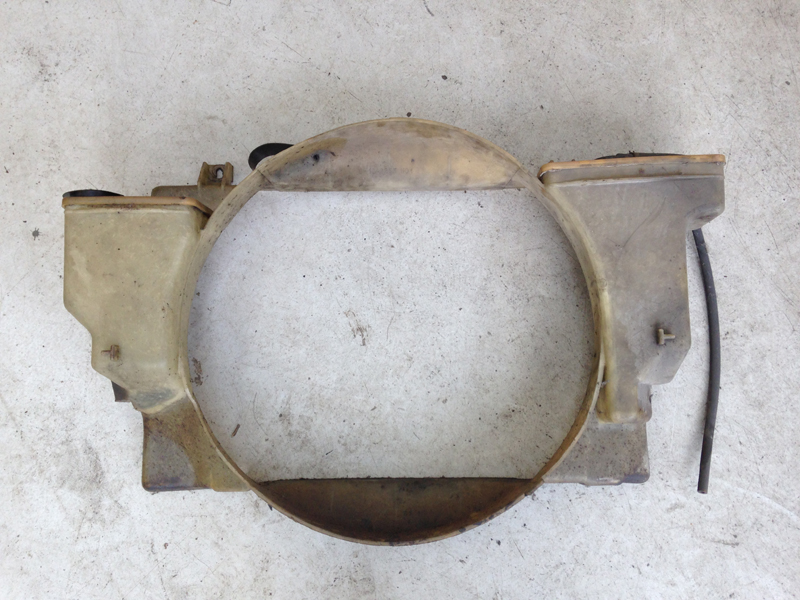
The original fan cowling was filthy:
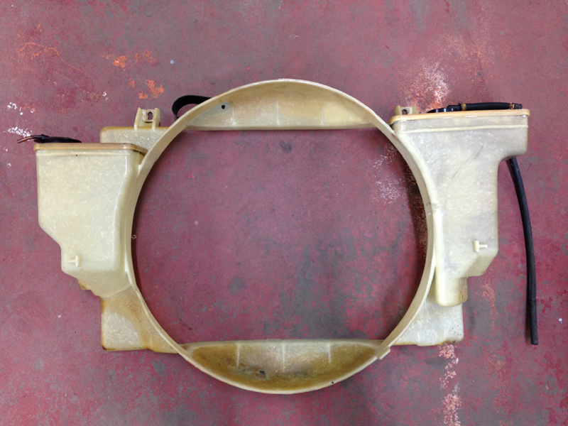
So we cleaned it up and gave it a quick polish:
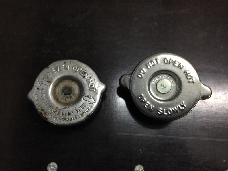
With the rebuilt engine and radiator and all new hoses we decided to replace the radiator cap for piece of mind too:
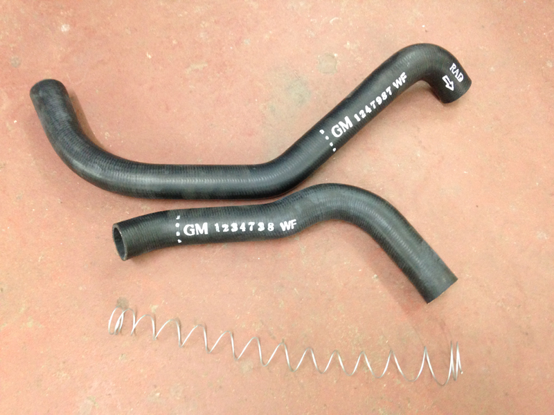
The new radiator hoses and anti-colapse spring for the lower hose. The originals were rock hard and full of dirt:
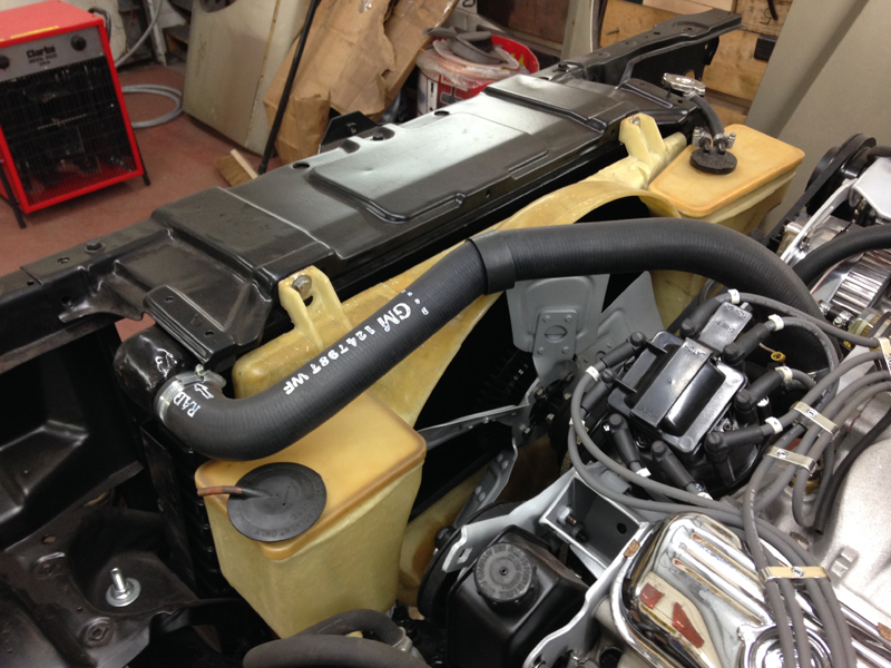
With all the replacement and rebuilt parts with us and the fronts of the chassis legs fixed we installed the radiator core support, the radiator, core support mounts, radiator insulators, top radiator support, fan cowling and the new hoses:
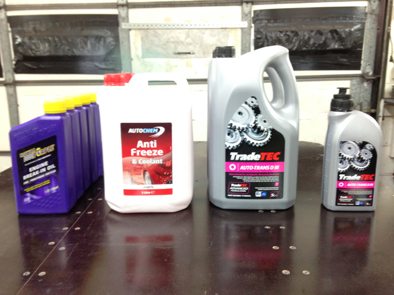
Next we filled the engine up with fluids, ran some temporary wiring to a battery, primed the oil and fuel systems, fired up the engine and carried out the camshaft break in procedure:
With the camshaft break in complete, we re-installed the inner valve springs back into the cylinder heads:
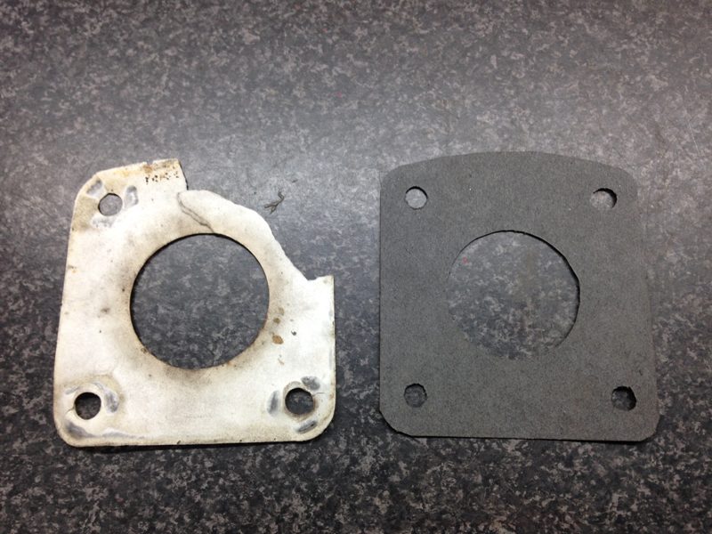
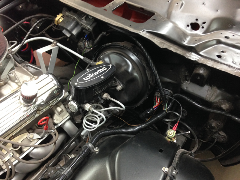
With the engine now up and running we moved on to finishing the brakes, first was to install the re-built servo and new master cylinder but the original gasket that mounts the servo assembly to the bulkhead was damaged so we made a new one:
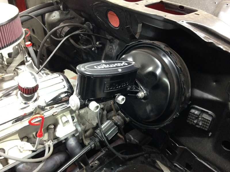
Then installed the new master cylinder and servo assembly:
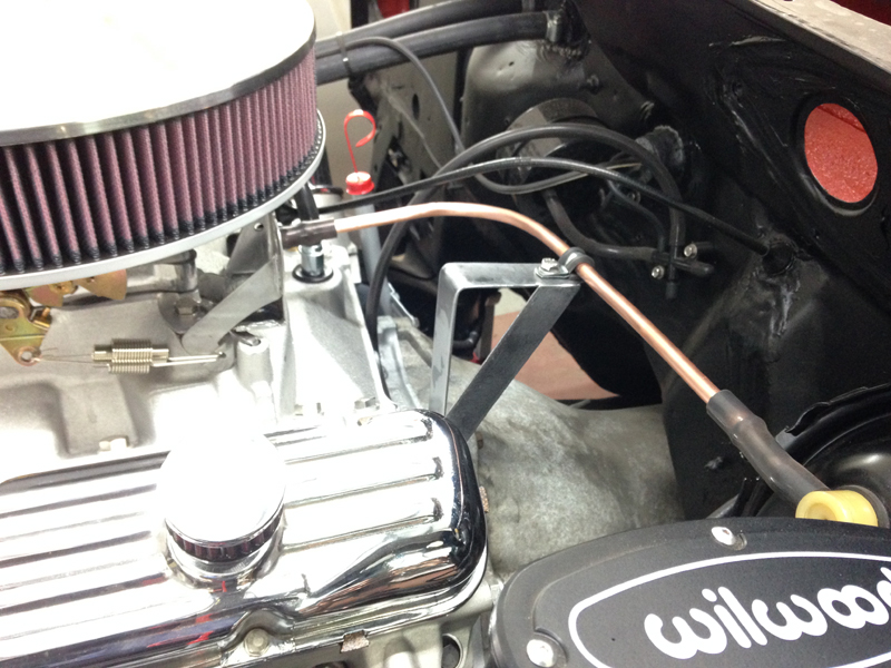
The original servo vacuum hose was perished and split and was also a long continuous rubber hose, for the best results a metal hard line should be used with short rubber ends so we fabricated this metal line and a support bracket for it:
Then fabricated new metal brake lines between the new master cylinder and the brake combination valve thats mounted to the chassis:
With the pedal end of the braking system complete is was time to move onto the wheel end of things, these were the original brakes that were on the car when it came in to us:
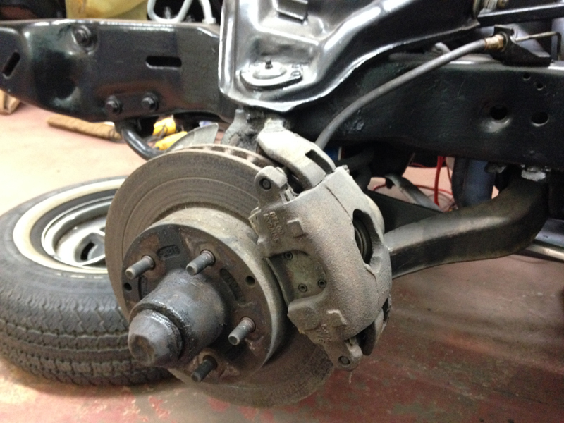
The first step was to remove all the original parts and degrease the spindle and the surrounding areas. One of the backing plates was also bent so we straightend it out:
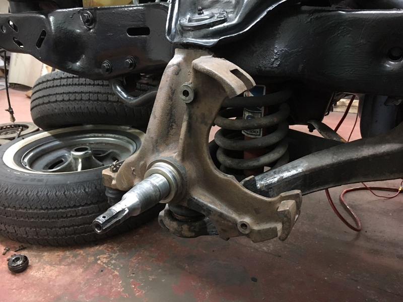
With the spindles all cleaned up we gave them a fresh coat of paint:
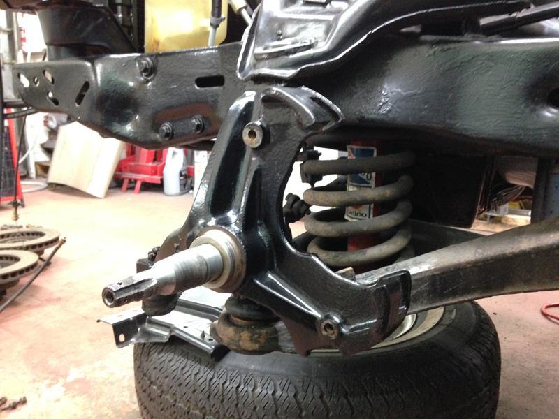
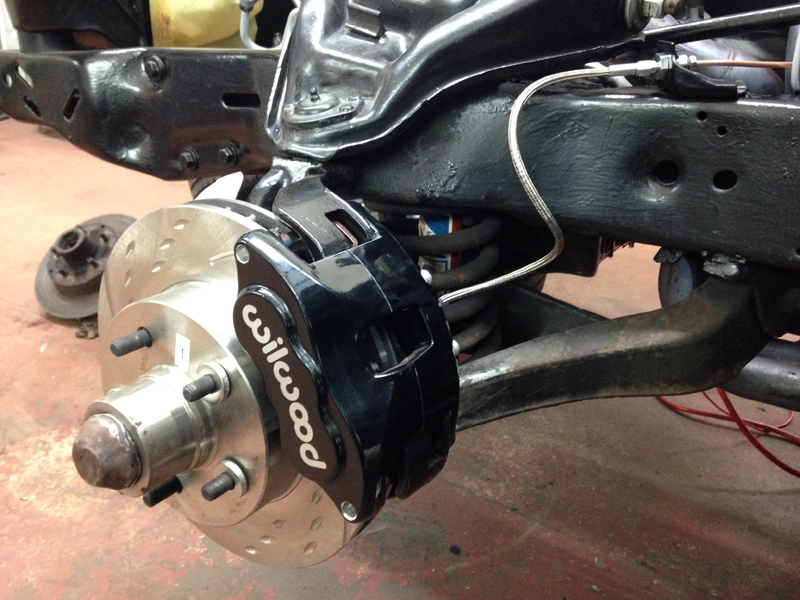
Then installed the new brake set up. The set up consists of new Wilwood D52 calipers, new grooved and dimpled rotors, new wheels bearings and new braided steel flexi hoses:
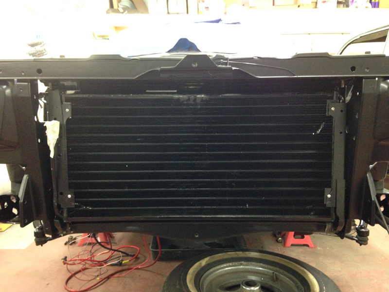
This is the original air conditioning radiator. I had visable signs of damage to it and signs that it may be leaking so we had it sent away for testing:
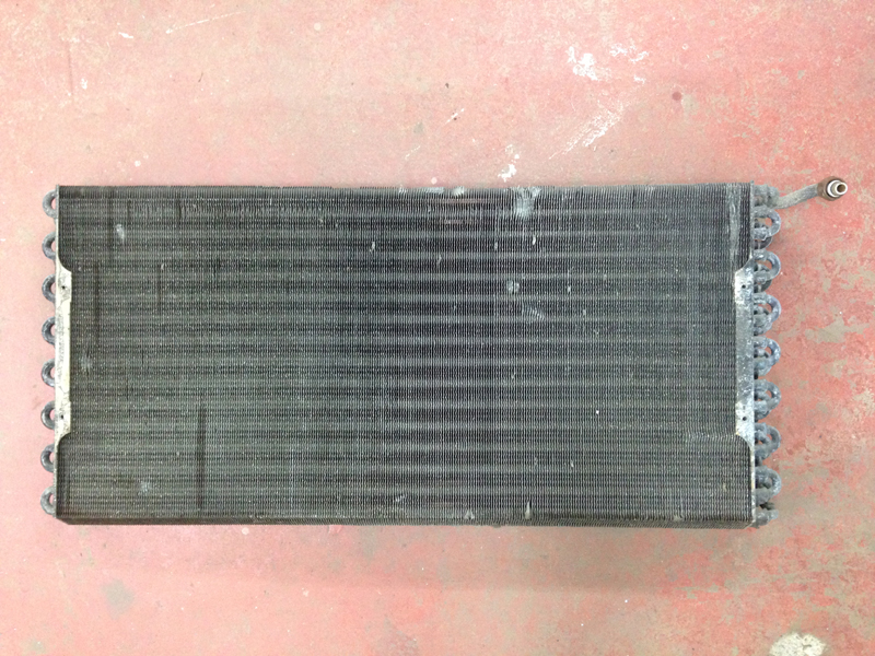
The test came back and showed it was leaking and the core was beyond repair so we had to have a complete new one built:
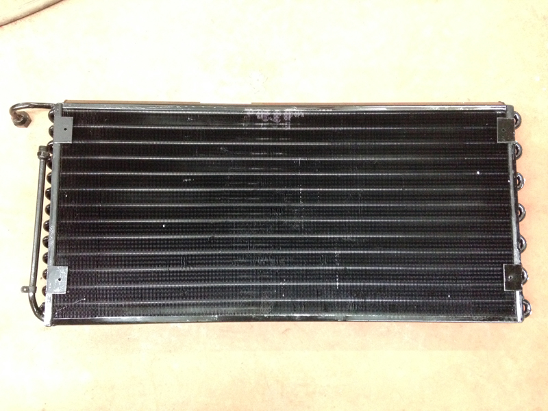
The holes that mount the radiator to the brackets which hold it onto the car didn't line up correctly on the new radiator so we had to mock it up and then once we were happy with the positioning of it, drill new holes in the radiator:
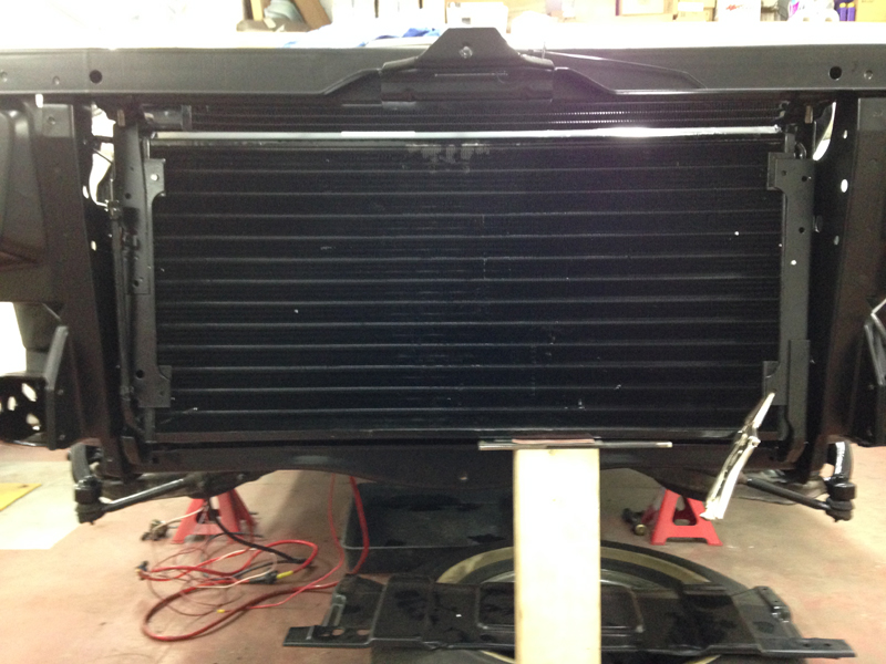
With the holes all in the correct place we could rivet the radiator back onto the original brackets that we had powder coated, then the radiator install was complete:
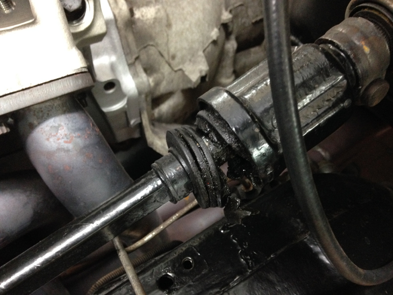
The original rubber boot on the steering column shaft was split and was leaking grease out of it:
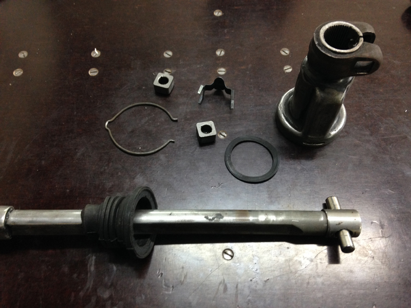
We removed the shaft from the car, stripped it down, cleaned all the components and then installed a new boot onto the shaft:
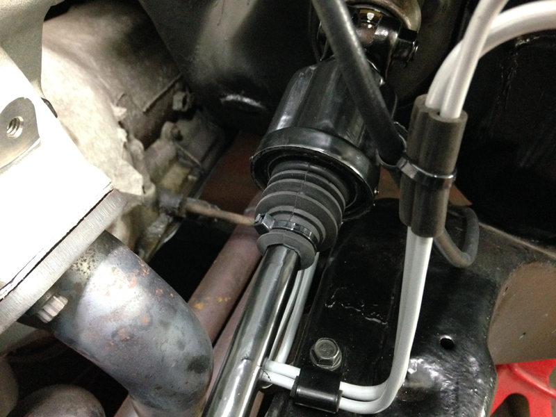
Then re-assembled the shaft with fresh grease, re-installed it back onto the car and gave it a fresh coat of paint:
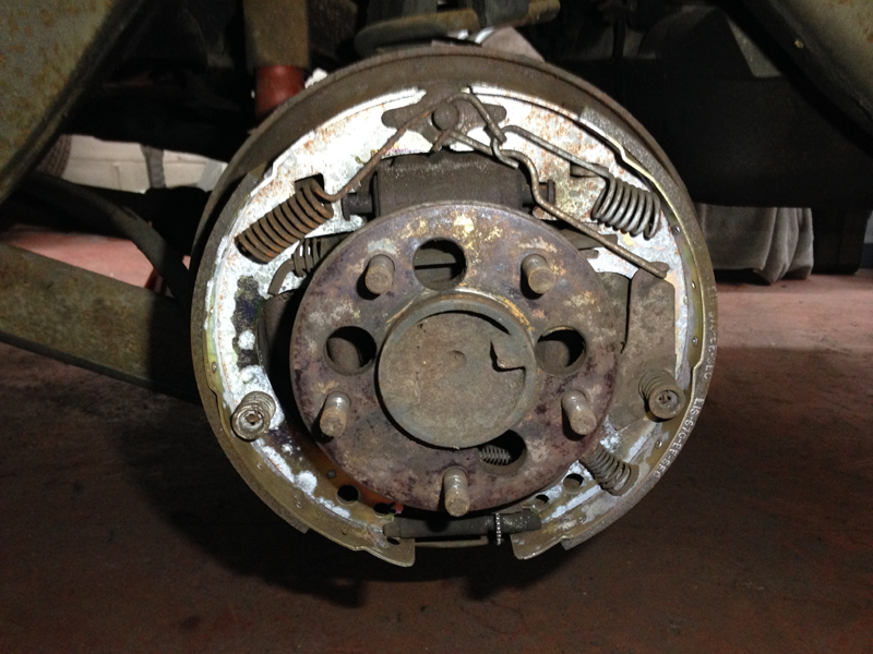
We then moved onto the rear brakes, with the front brakes and master cylinder all re-built and new it only seemed right to check out the rear brakes. The brake shoes looked to be previously replaced just before the car had been parked up and the drums were in good condition but the wheel cylinders were showing signs of leaking:
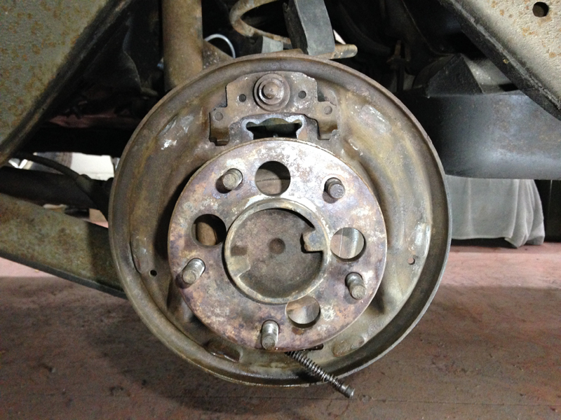
We completly stripped the rear brakes down and cleaned everything up:
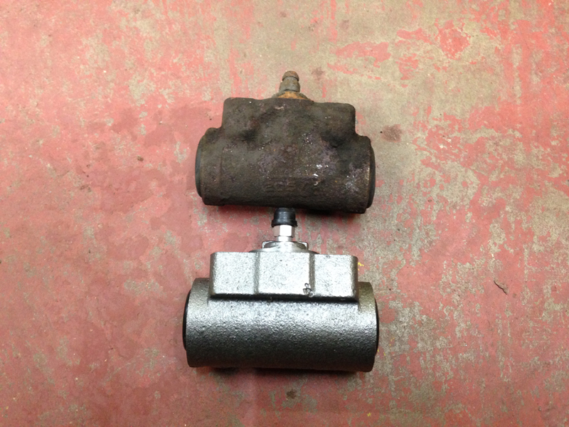
We sourced new wheels cylinders for the rear:
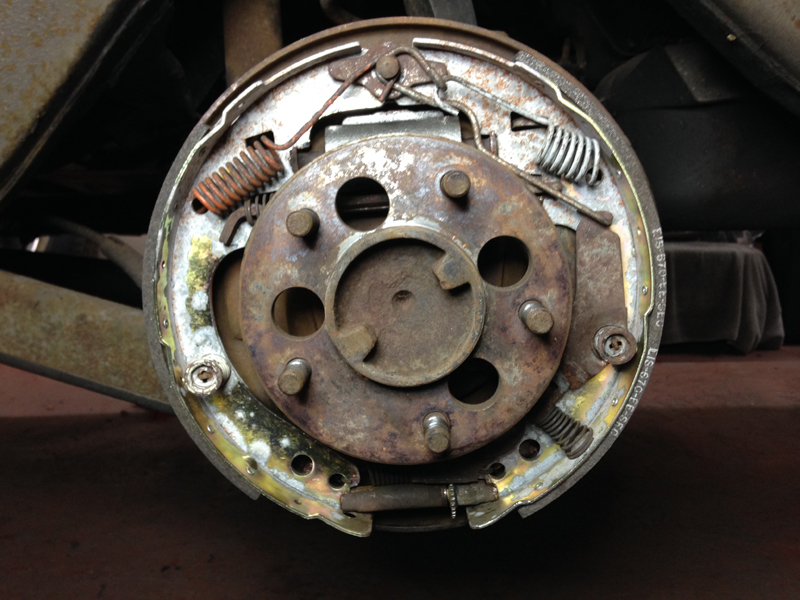
Then re-assembled the rear brakes and adjusted them up correctly:
We also replaced the rear brake hose with a custom order braided stainless one that matches the new front ones and re-newed the metal hard lines that run across the rear axle to either wheel. Then we filled the system with fluid and bled the system free from air. The result is a nice firm pedal that will stop the car much better than when it was new:
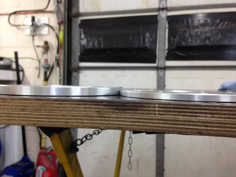
One last issue to address regarding the brakes was that the original 15 inch wheels didn't quite fit over the new brake calipers, they needed minimal clearance to fit. The owner of the car plans to upgrade to 17 inch wheels in the future but for the time being a solution was needed so we worked out that if we spaced the wheel away from the caliper by 6mm the wheels would have the clearance they needed, so we ordered some wheel spacers:
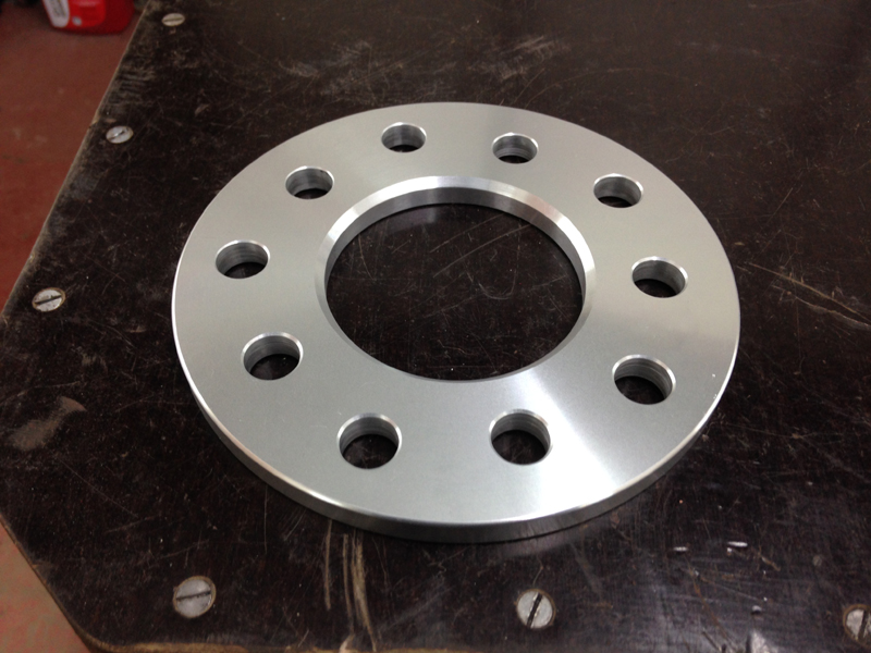
The sizes go up by 5mm at a time, being that 5 was the smallest ammount to small we went for the 10mm thick ones and had them machined down to 6.5mm to allow for any heat expansion. When the owner of the car gets his new wheels he will no longer need the spacers and can run the new wheels without them, but for now this is a fix that lets us use the original wheels over the upgraded brakes:
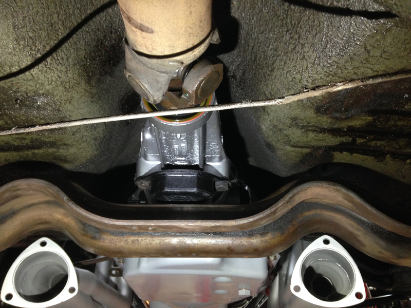
With the brakes completed we wanted to take a look at the new exhaust manifolds and a problem that had been bothering us for a while. The angle at which the new manifolds exit is totaly different to the factory angle, now if you plan not to run any exhaust system on your car this isn't a problem, but for us it was. The plan was to run a full exhaust on this car and the angle the manifolds exit at means the next section of pipe would run straight into the transmission crossmember, here is the driver's side:
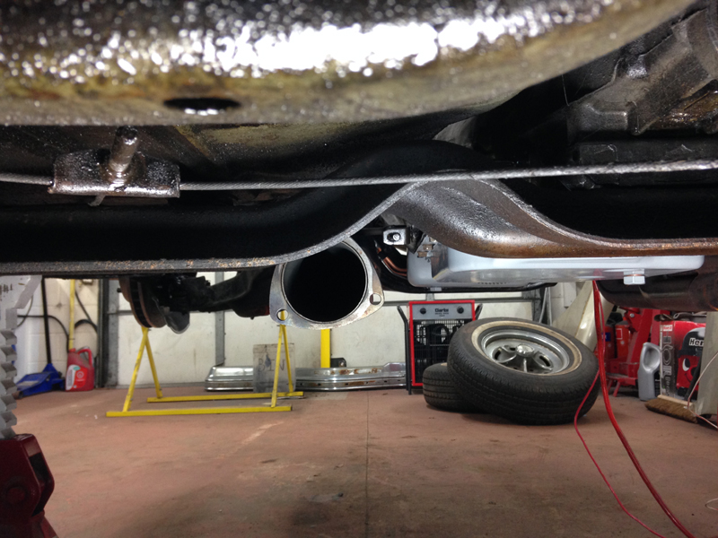
And the passenger side:
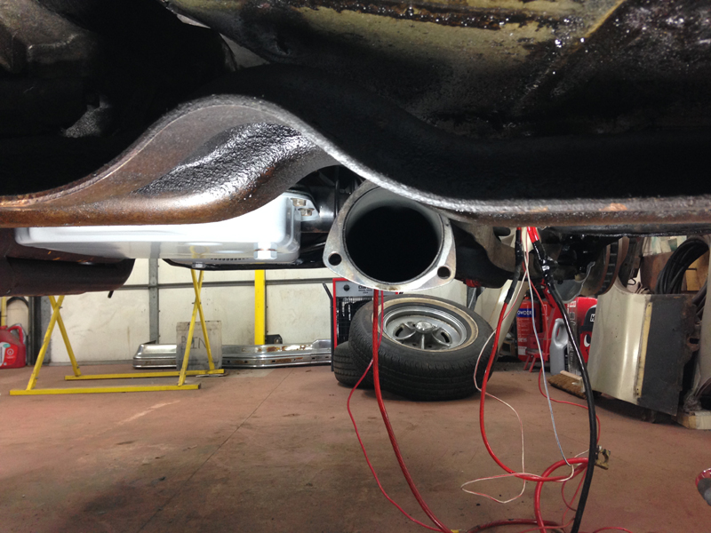
We came up with 2 solutions to this problem, the first was modify the new manifolds, the 2nd was modify the crossmember. After some thinking, modifying the manifolds seemed like the quickest option, so we cut of the end section of the manifold, then cut the removed section at the desired angle needed to make the exhaust point into the crossmember's raised section for the exhaust to pass through, then tack welded the manifold back together to check the fit and see if it fixes the problem:
Now the exhaust passes through the crossmember at the correct point and the crossmember retains its factory design, this means we can now move onto making the next piece of the exhaust system:
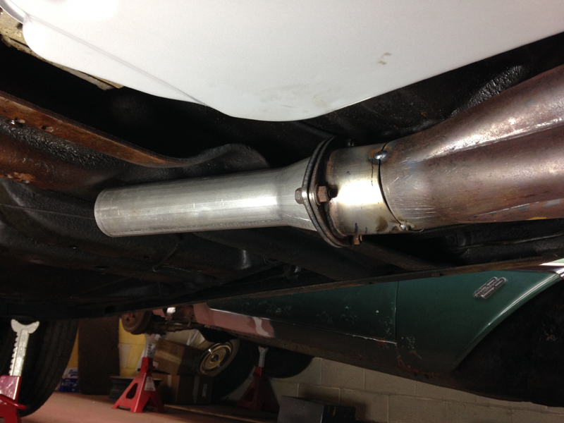
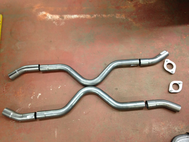
For the exhaust system itself we wanted to run an X pipe design which would be removable without having to take the entire exhaust system off the car, so that if the transmission or driveshaft needed any maintance, it wouldn't be such an involved job. So we done some measuring and orderd some pipe work:
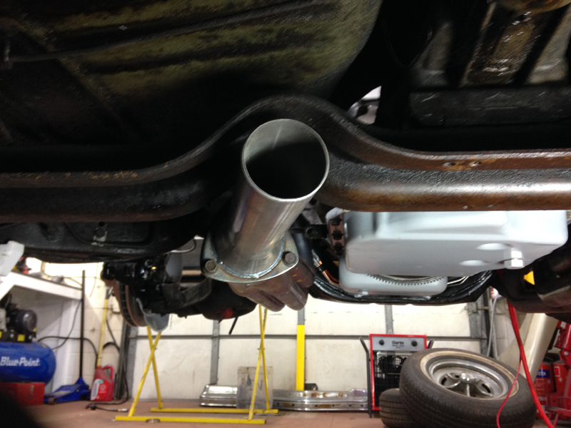
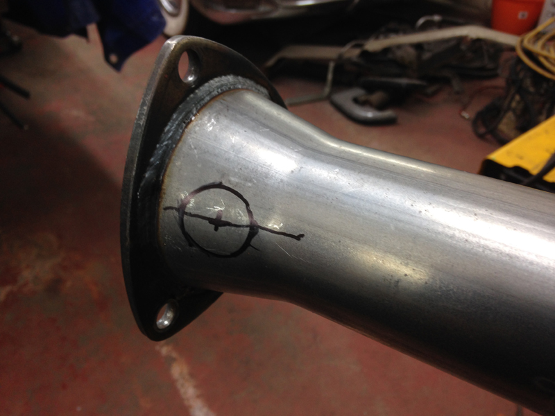
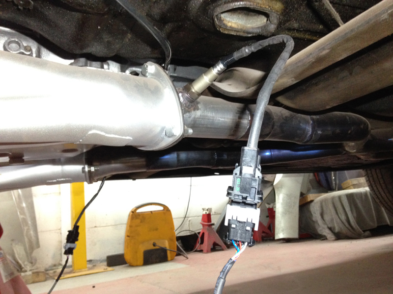
We also wanted to include an oxygen sensor bung in the new system for 2 reasons. 1, so that in the future if the owner wants to convert the car to a fuel injection set up, the exhaust is already done for him and all that would need to be done would be screw in the oxygen sensors and 2, we can finely tune the engine and monitor what its doing with an air/fuel ratio monitor. So first up we marked out where the sensor bungs would go:
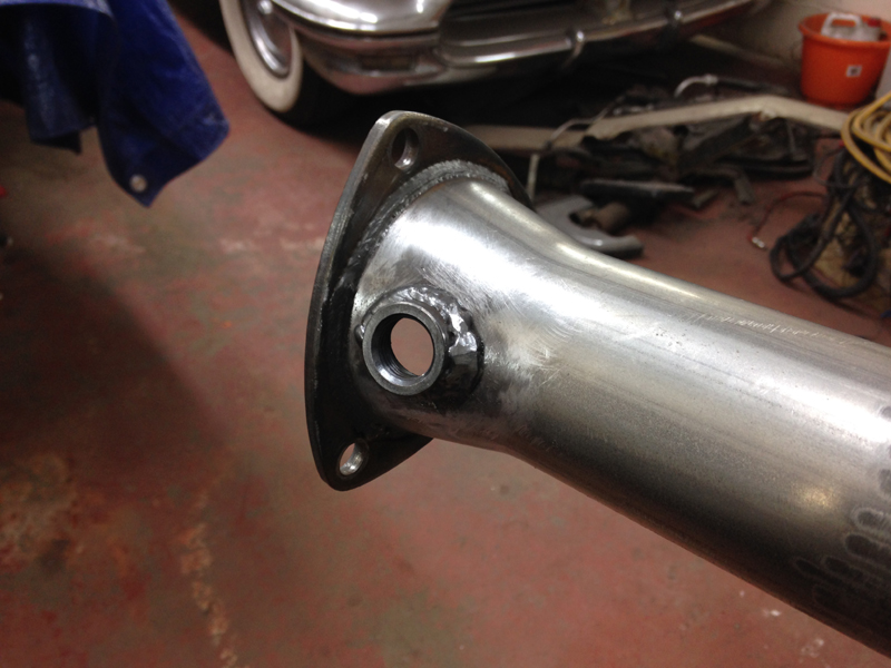
And then welded the bungs in place. When the sensors are not being used a threaded bung blocks off the hole neatly:
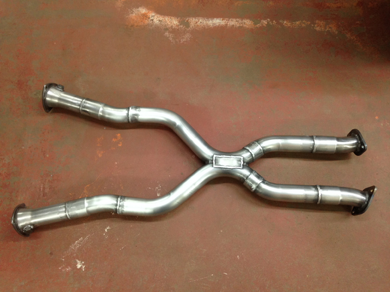
Then with some cutting of pipes and measuring we fitted all the pieces of the X pipe section in place, tack welded it together, then removed it from the car and finished welding it up. We used a rectangular plate on the top and bottom of the X section just to add strength to the set up, all the other joints are sleeved so have the strength in them but there is no way to sleeve this type of X design so we just add the places after to prevent cracks in the future:
We then removed both manifolds from the car so that we could finish welding them up. Again we added a small metal plate over the join on the top and bottom just for strength as again, it wasn't possible to sleeve this join due to the change of angle:
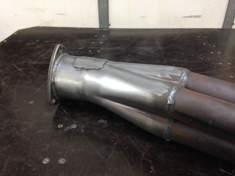
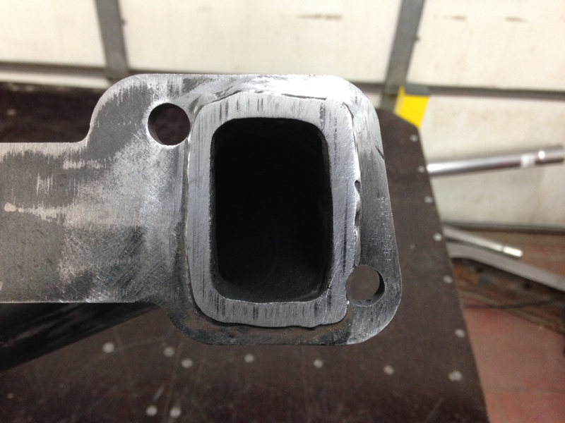
We noticed when we removed the manifolds that the driver's side one had a slight blow on the gasket. This was being caused by the gasket face not having enough material where it meets the gasket:
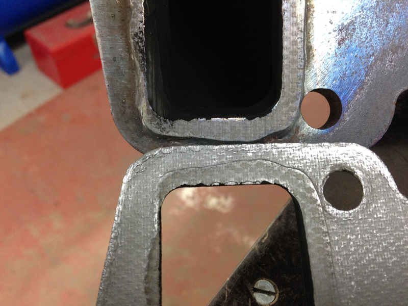
So we done some welding to the gasket face of the manifold the carefully filed it by hand back down to ensure it was 100% flat so that it makes a tight seal. This should now seal properly and not cause any future issues. Now that the manifolds are finished and with the engine been run already we can send the manifolds away to have a ceramic coating applied to them:
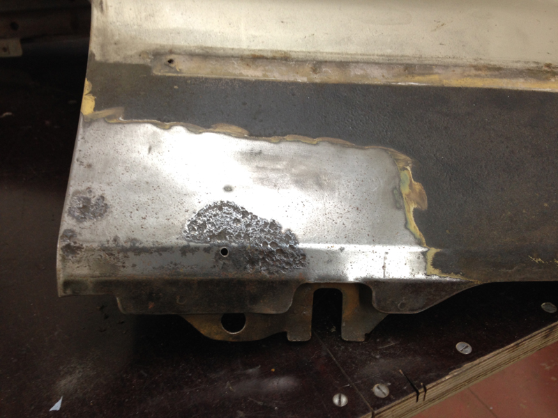
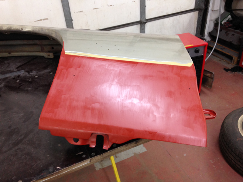
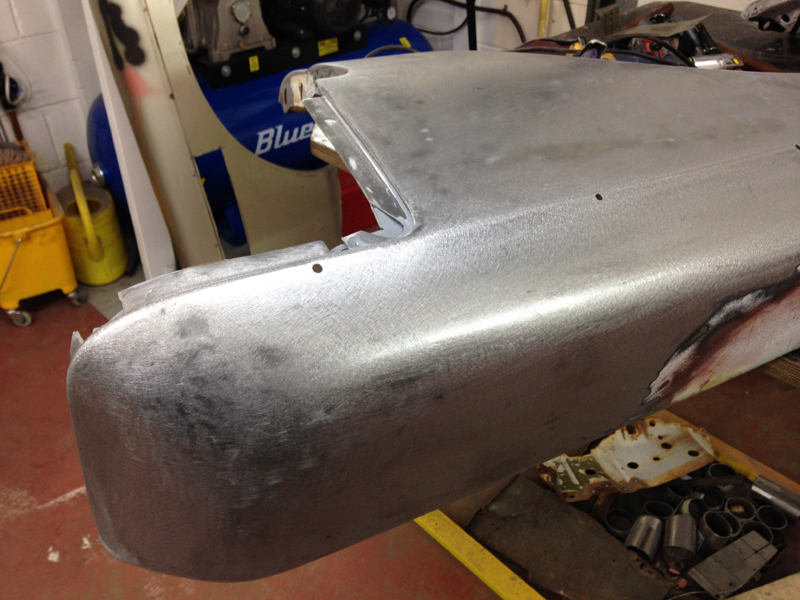
With the manifolds being away we decided to make a start on the rust repair work on the front wings. This is the lower rear edge of the driver's wing at the front of it. The paint had blistered and bubbled up so we decided to take a look under the paint. Even though it didn't reveal any rust holes the area was heavily pitted and had it been left would eventually rot away. The best thing to do with this type of thing is to fix it now before it gets worse and spreads:
The first step was to cut out the rusty section:
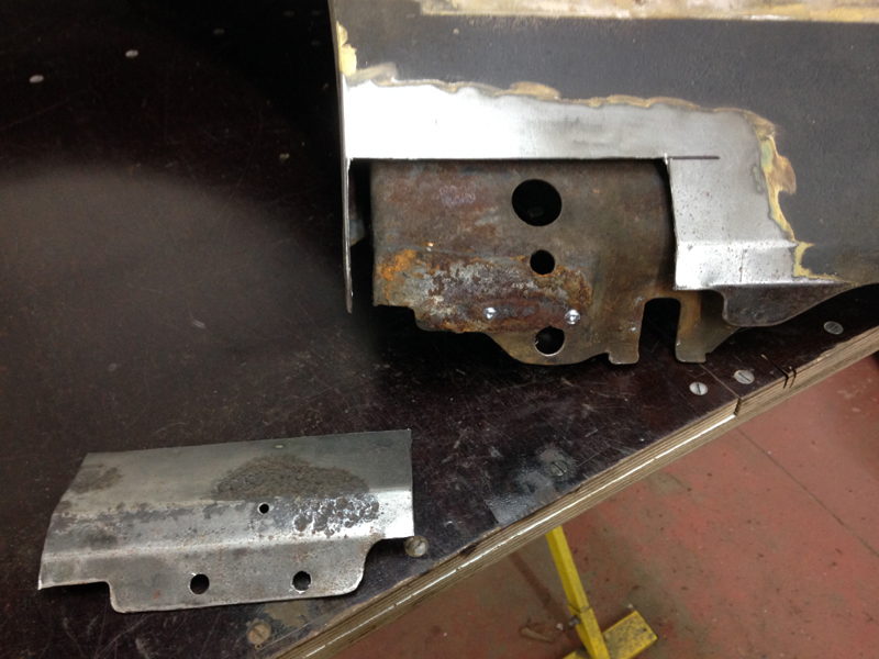
Then grind back all the surface rust on the support section behind the outer skin and fabricate a piece of steel to be welded back in place:
After checking the replacement section fits, we coated the back of it and the front of the support section with a weld through primer to help with future rust protection since these areas are pretty much inaccessible once the new piece is welded back in:
Then we welded the new section in and ground the welds flush. Thats the repair for this area complete for now:
We removed the paint from the rest of this lower edge just to be sure there was no more problems hidding. Even though there was nothing visable with the paint on, the rear part of this section had several holes in it under the paint:
After cutting the affected area out we could see the rear of the outer skin was heavily rusted from being sandwiched agains't the support section:
First up was to grind all the rust out of the support section and get it cleaned up and usable again:
Then give it a coat of weld through primer. This can be drying whilst we fabricate a repair piece for the outer skin:
We finished the repair section and gave that a coat of paint on the rear of it too:
Once the paint had dried we welded the new piece in place and ground the welds flush:
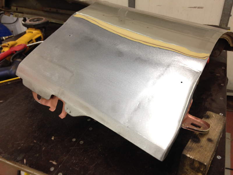
For now this wing is finished so we gave it a coat of brush on rust proof primer just to stop it going rusty and then put the wing to one side until the rest of the welding repairs on the cars body are complete. Eventualy we will have all the removable panels soda blasted to remove the rest of the paint so that we can start prepairing the car for its new paint job from a fresh base:
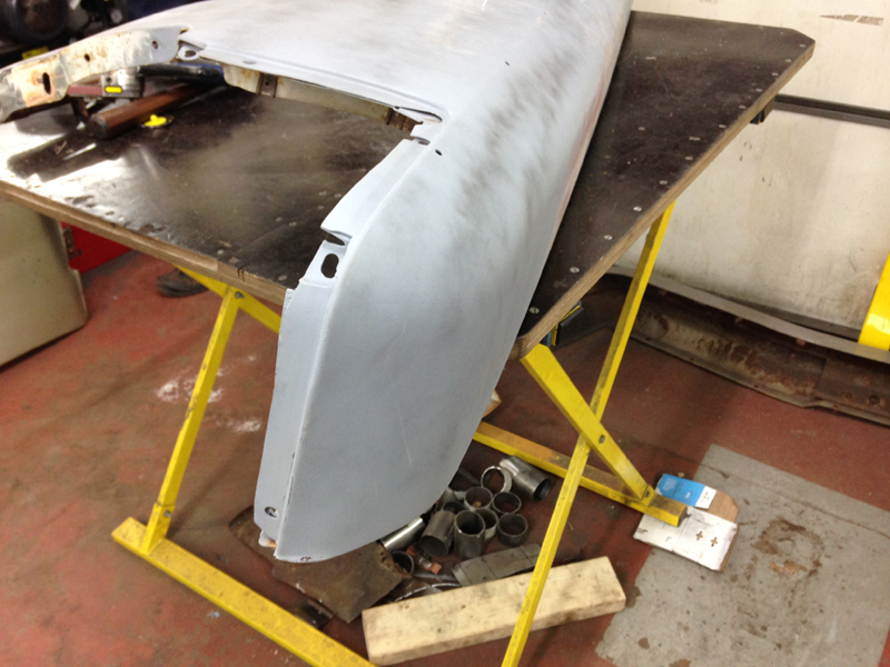
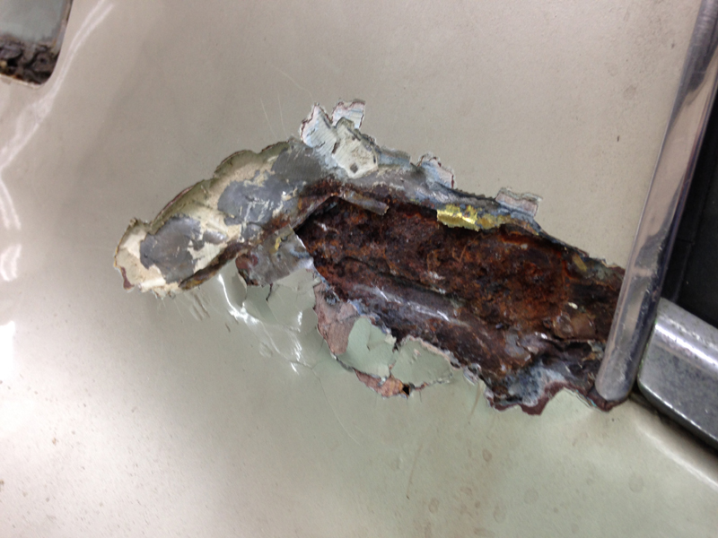
This is the passenger wing that was on the car when it came in, unfortunatly it was not the cars original wing and we think it was replaced when the car took a knock on that side somepoint in the past. Unfortunatly who ever replaced the wing either used one that was rusted out to start with or wasn't aware that it was starting to rust. Here is the same section that we just repaired on the driver's wing but on the passenger side, its totaly rotten and full of dents:
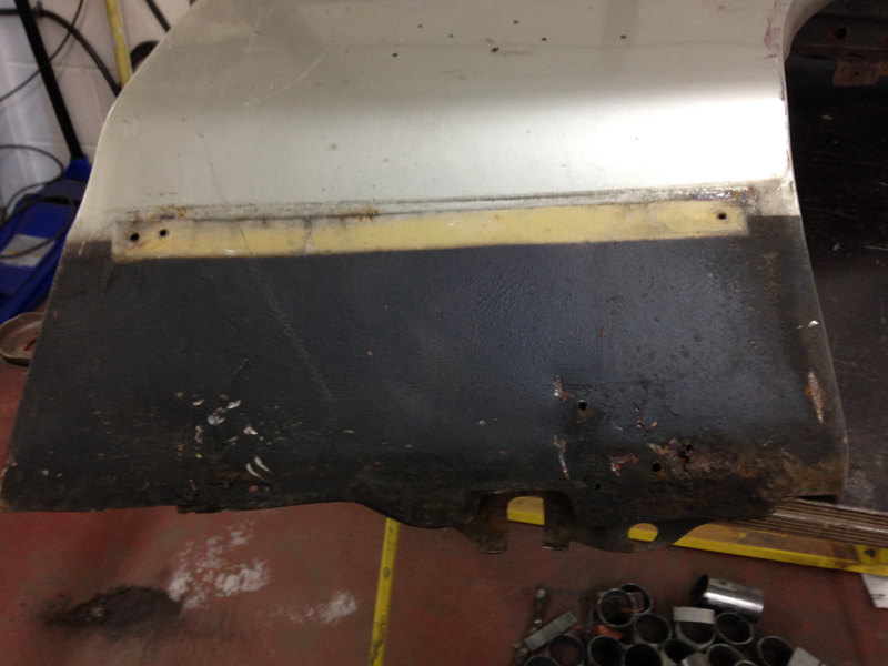
This is the front section of the passenger wing where the headlamp fits:
And this is the bonnet jamb edge along the back:
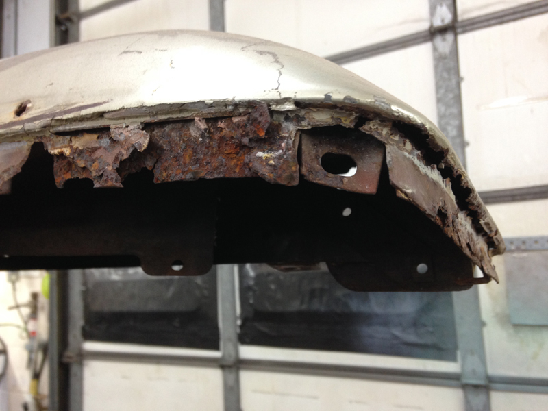
The story continued throughout the entire panel, it was rotten all over and full of dents hidden under the paint work. Yes this panel can be repaired but we decided it would be cheaper for our customer in the long run if we sourced a replacement wing to use as a better starting point. New panels are not available for this car so we found a good used one and imported it from a dry state in the USA:
Even though the replacement panel is a much better starting point it still required some work to get it up to the standard required to be used on this car, after all it is a 44 year old part. We removed the paint on the lower rear edge, the same as on the driver's side wing and found some dents and some heavy pitting. The 2 holes for the trim piece had been filled so we drilled those back out:
On the rear of this area is a support section which strengthens the panel and mounts it onto the car. The mounting point has somehow been twisted and torn the steel and a piece of it is actually missing:
So the first step was to drill out the spot welds on the support section on the rear and remove it completely. Then cut away the rusty section of the wing itself and knock all the dents back out:
We then fabricated a new repair piece to be welded into the wing and then welded it in place:
We decided to use the rear support from the original wing that was on the car. Since the rest of the wing was going in the scrap and the support section was in good condition we removed it from the wing. The top one is the piece from the new wing thats damaged, the bottom is the un-damaged one from the original wing. Here you can see the damage between the two:
The first step was to test fit the original piece in the new wing to see how it fit. After some fettling we had it fitting perfect:
Then we removed the support section and cleaned up the area of the wing that it covers:
Then coated it in a rust protective coating. The areas left without any paint will be coated in a weld through primer, if we had coated these areas in the red paint it would have just burned off when welding the support section back in and cause the paint left in the surrounding area starting to peel off:
We cleaned up and coated the underside of the support section in weld through primer too and then coated the back face of the wing itself in weld through primer, then proceeded to weld the support back in and grind the welds down. This area of the wing is now complete:
One of the square nuts which are welded into the wing that mounts it onto the inner wing was missing:
So we took one from the original wing and welded it in place on the replacement wing:
The front edge of the replacement wing was painted in primer when it arrived and looked like someone had been doing some body work to it prviously:
Being able to feel some dents on the rear side of the wing and visably seeing some areas that were not quite right we decided to take all the primer off. During this process we found lots of filler in the panel which we also removed back down to the bare metal. Here you can see several low spots which were just filled over:
The very front section had a crease in the panel too:
These dents can easily be fixed but another support section is in the way:
So again the first thing we done was drill out the spot welds and remove the support section:
With the support out the way we can access the metal from behind and reshape it back into the correct shape:
We addressed the other dents that were in this area and then cleaned up the metal on the wing and the support:
Then applied a rust protective coating, followed by stonechip, followed by the weld through primer to the wing and the support:
The finally welded the support section back into its original place:
With the rust and dent repair work completed on the replacement wing for the passenger side we went back to the driver's side wing. We wanted to check the front edge under the paint to make sure there was no horrible supprises. We found some small rust holes and a few dents in the front edge:
So we welded up the holes and sraightend the metal out:
We also removed the support section from the front edge of this wing too so that we could clean all the surface rust out from the wing and the support, then apply rust prevention measures to stop further rusting and then weld the support back in place:
Then applies a rust preventive primer over the bare steel areas to stop rusting for the time being:
Same on the front edge on the outside:
We ended up taking the entire replacement passenger front wing back to bare metal all over the outer face and removed all the dents and made sure no other rust issues were under the paint. Because the entire wing was bare we sprayed on the rust preventive paint just to stop it going rusty whilst its sitting about in the workshop. This wing is now as good as new:
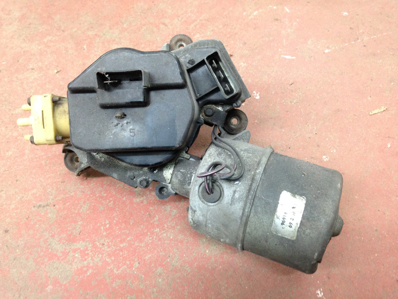
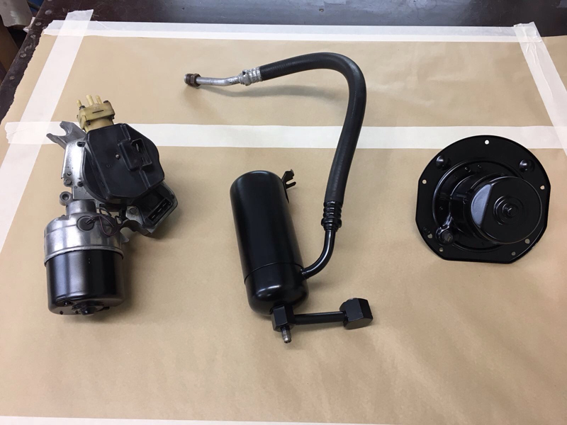
Now that the weather is starting to warm up a bit we could concentrate on getting of the remaining parts put back into the engine bay. These all needs a good clean and painting again. First up, the wiper motor:
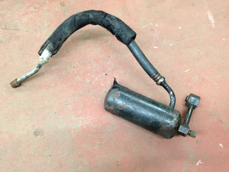
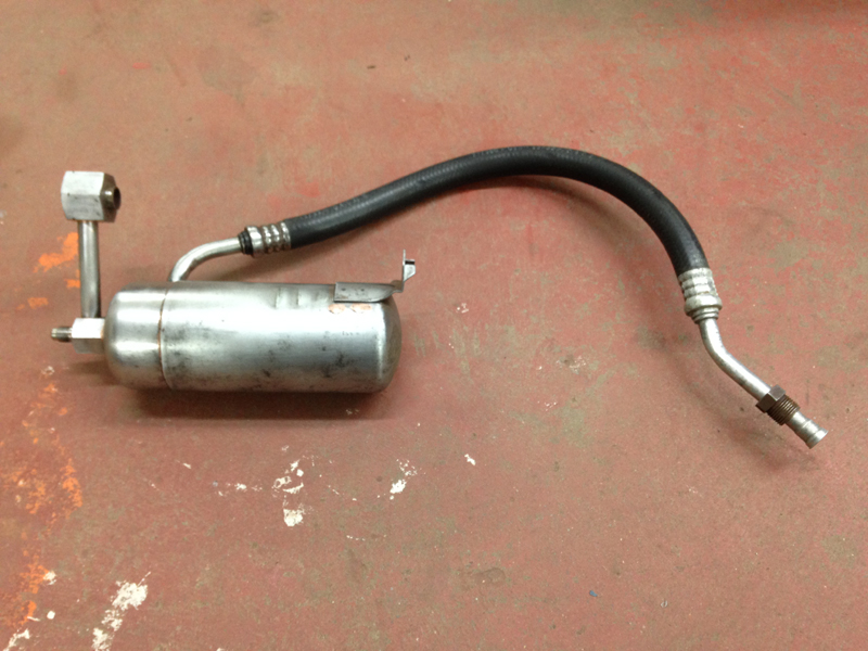
The air conditioning gas resonator/chamber:
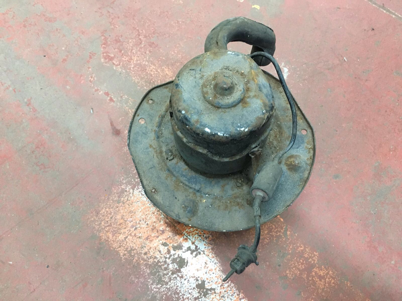
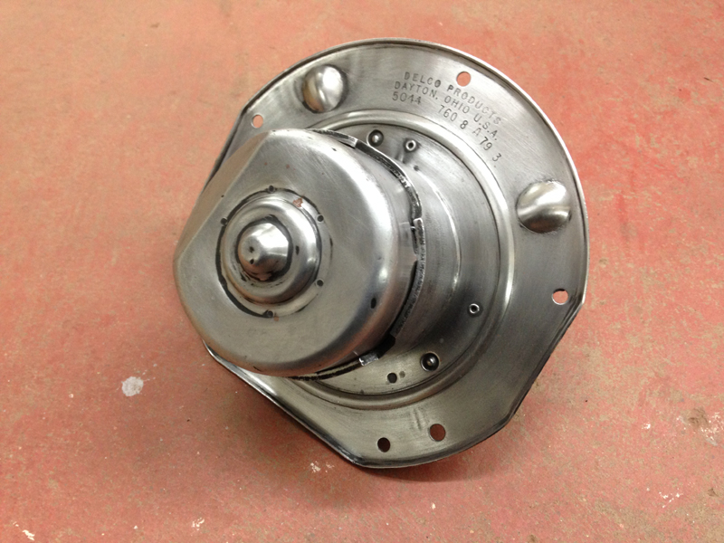
And the heater fan blower motor:
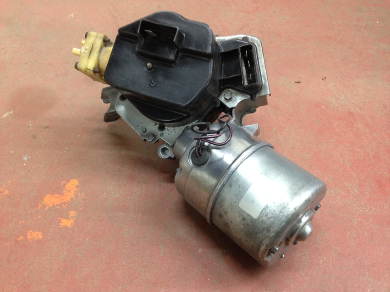
The wiper motor all cleaned up:
The air conditioning gas resonator/chamber:
And the heater fan blower motor:
And after they have all been given a fresh coat of paint:
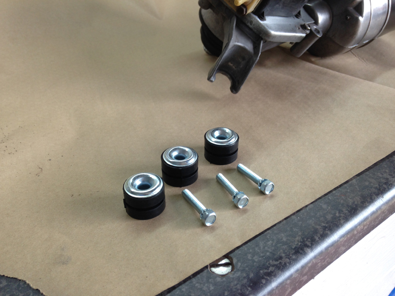
We had a new mounting kit for the wiper motor as the original bushes were split and one of the bolts had snapped during removing the motor which we had to drill out and re-tap the thread:
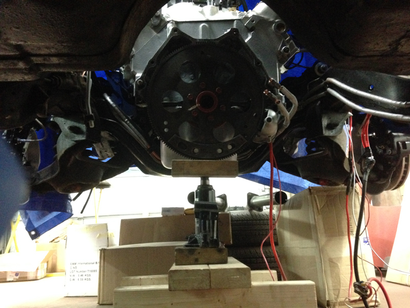
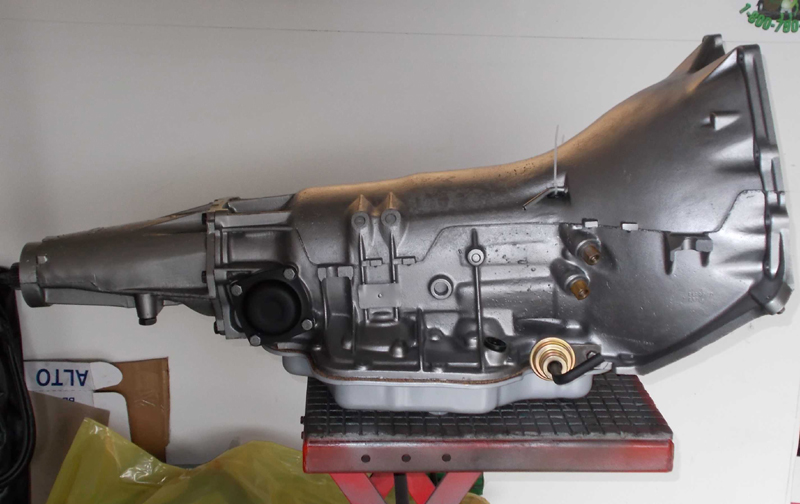
Ever since firing up the engine and putting oil in the transmission for the first time in 17 odd years, the transmission has not stopped leaking oil from just about every single seal on it and has continuously been making a mess on our floor! The plan with the car was to always have the transmission rebuilt in the future with some upgrades once the car had been driving for a bit, but since it was leaking so much we thought it best to do the rebuild now. The first step was to pull the transmission out of the car:
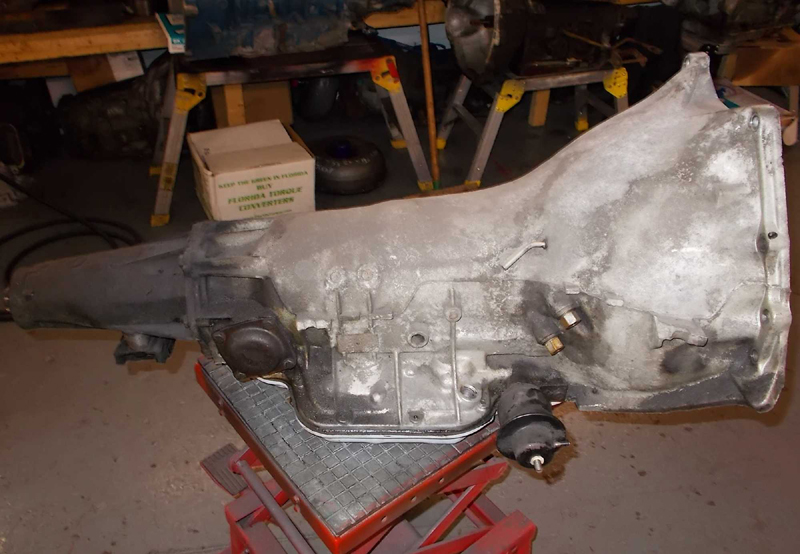
Here is the transmission out of the car and dropped into our trusted transmission rebuild shop awaiting its rebuild:
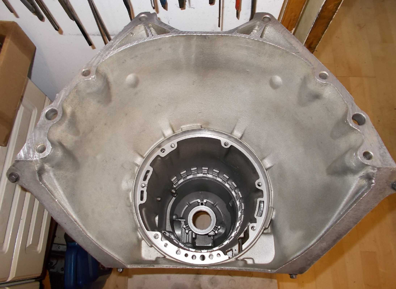
The transmission completly stripped down:
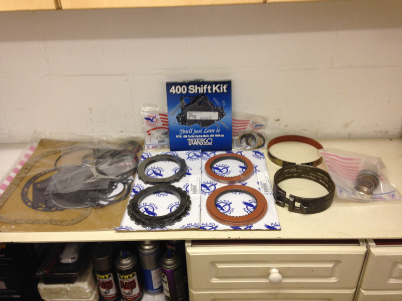
Here is the new parts for the transmission, we went with upgraded clutches and a shift correction kit to improve the performance of the transmission:
Here is the transmission all back together and fully rebuilt:
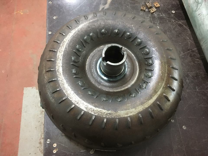
There were a couple of problems with the transmission, the first was that one of the bands had gotten a little hot at some point and was a little burnt but a new one was supplied in the rebuild kit. The second problem was a little more concerning, the transmission had the wrong torque convertor fitted to it. Someone had installed a switch pitch type torque convertor but not converted the rest of the transmission to a switch pitch transmission. This had caused wear on the torque convertor and the input shaft of the transmission. The rebuild shop replaced the shaft with a good used item and we would have to source the correct torque convertor:
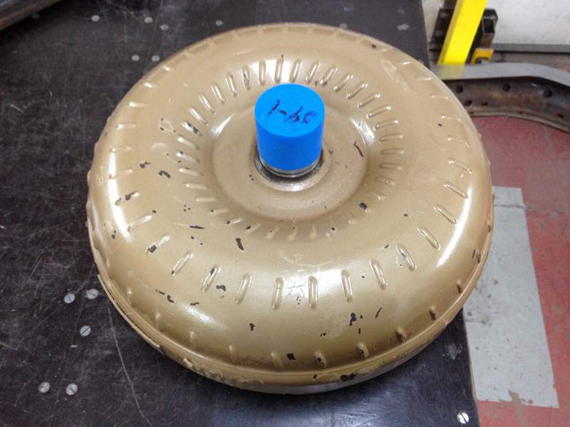
This is the correct replacement torque convertor for the car:
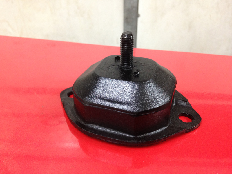
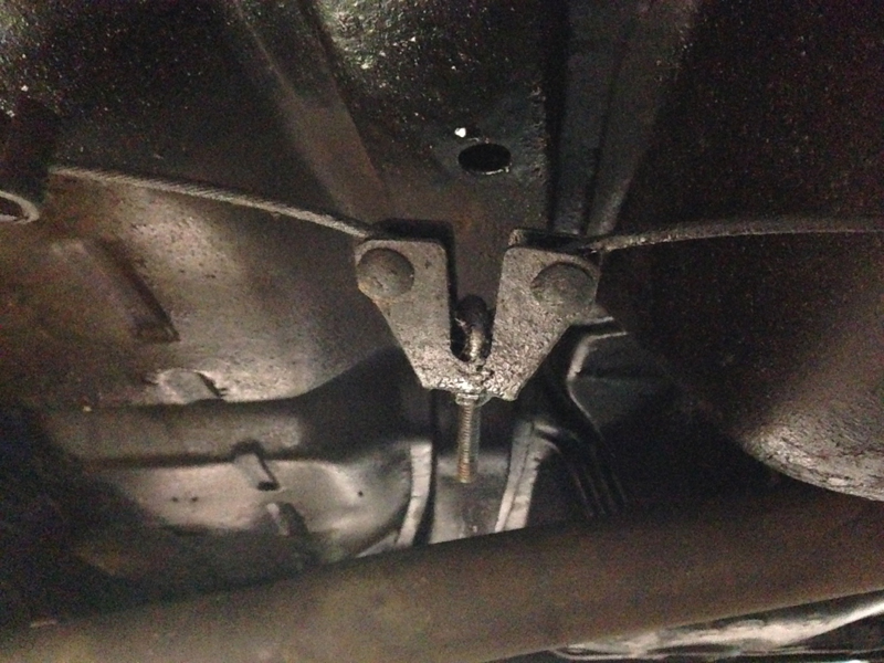
The last job before re-installing the transmission back into the car was to replace the mount for it as the original was completly soaked in oil and falling appart:
With the transmission sorted out and back in the car and now the exhaust manifolds back from being ceramic coated the next step was to get them back on the car:
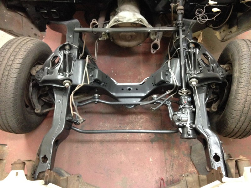
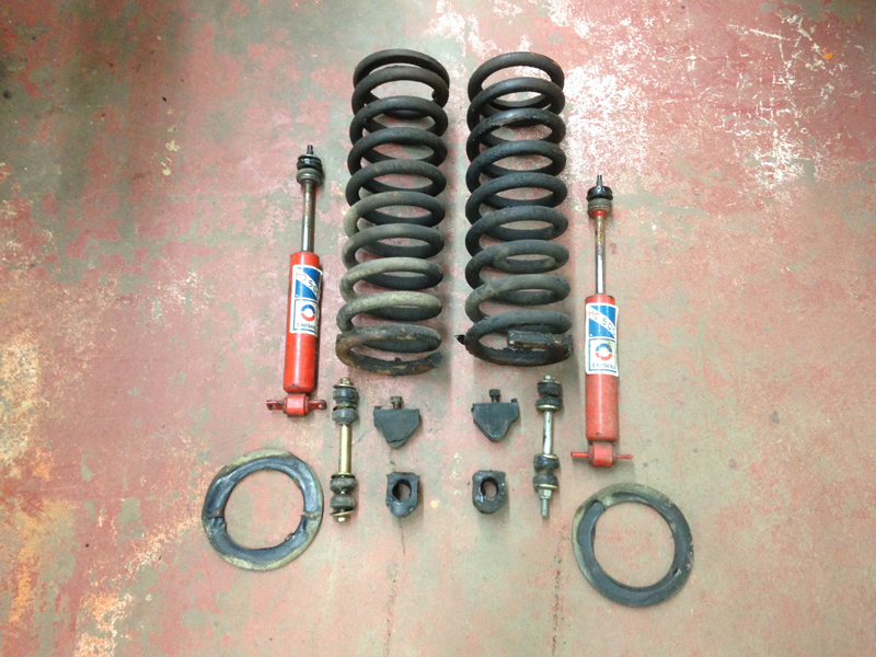
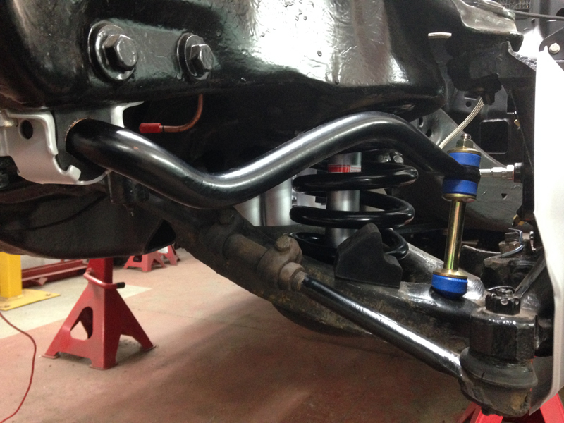
Next up was to get the new suspension parts onto the car and out the way, we will start with the front suspension:
Here are all the components removed that we will be replacing:
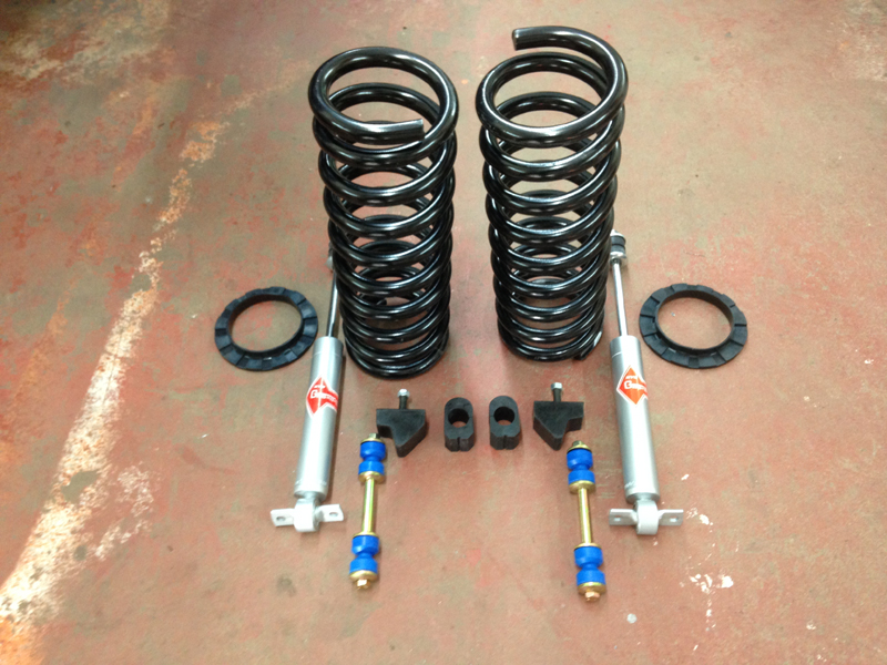
And the new parts ready to be fitted:
Then installed on the car:
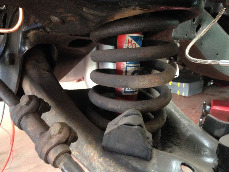
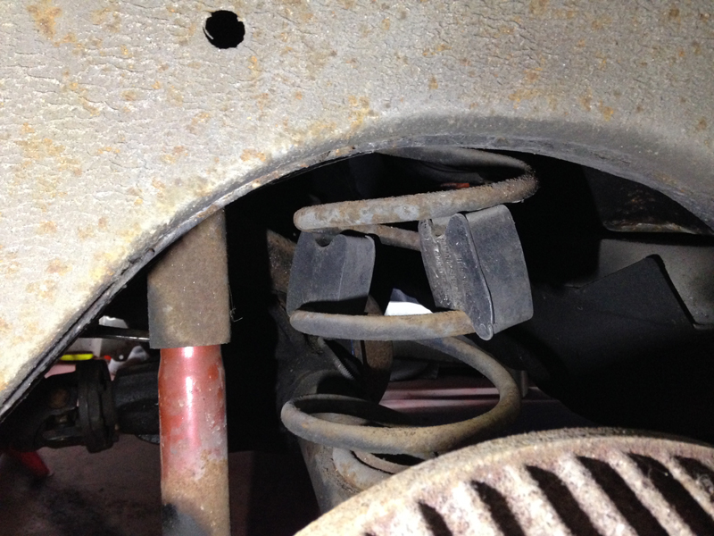
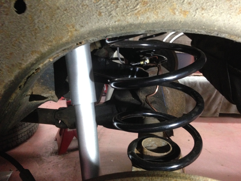
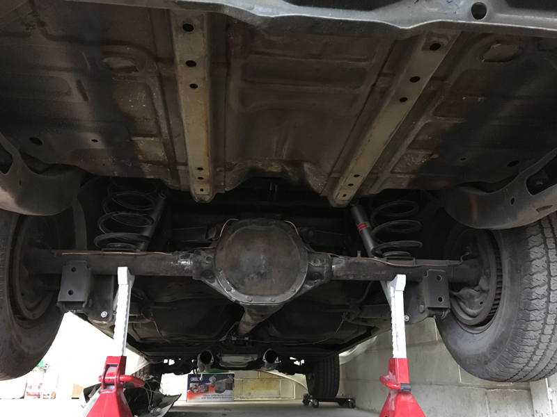
With the front finished we can move onto the rear. Someone had added rubber blocks between the coils of the rear springs which have sagged over the years to try and increase the the ride height back up to how it should be. Also one of the suspesion arms was bent:
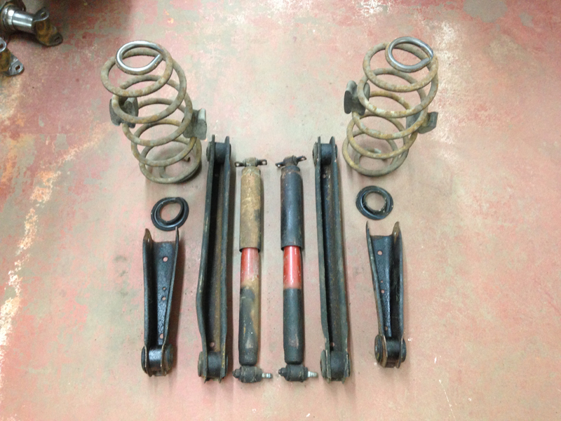
Here are all the old parts removed. You can see the damaged suspension arm in this picture:
These are all the new parts ready to go on. We went with some upgraded 4 sided box suspension arms, this will help prevent the rear axle from twisting when launching the car hard of the start line:
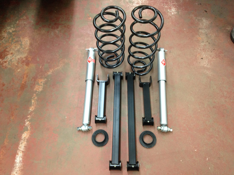
All the new parts installed on the car:
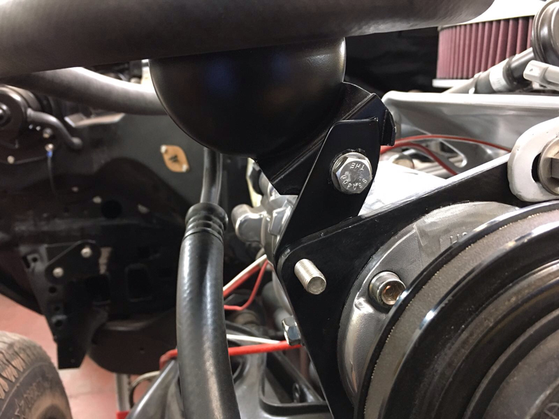
We went to install the freshly painted air conditioning gas resonator/chamber but due to differences in the after market pump the mounting location didn't line up:
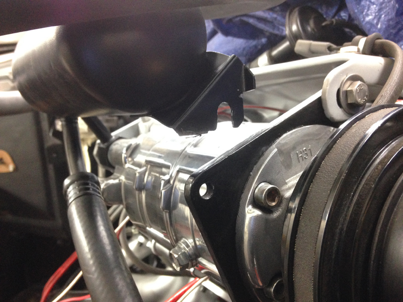
So we fabricated a small bracket to go between the 2 mounting points, painted it black and then installed it:
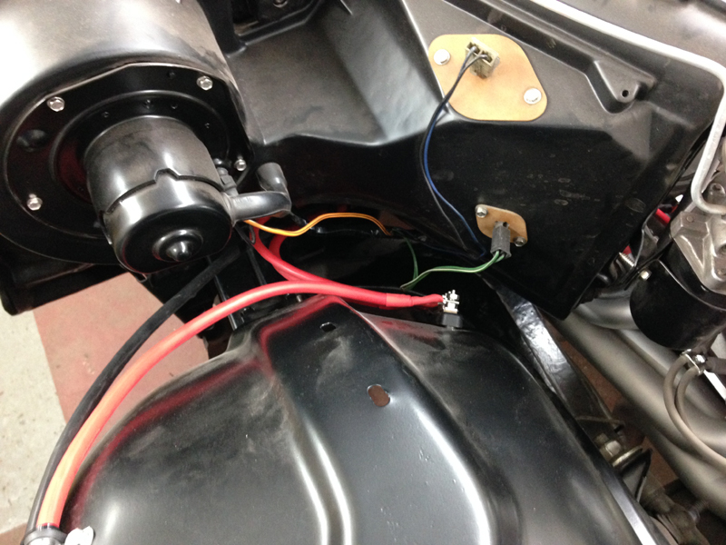
The factory body earth strap is a thin cable the runs from the back of the intake manifold to the bulkhead and fixes to the car using a sheet metal screw. This design is fine when the cars are new but over the years causes the screw can come loose or rust build up between the screw and the bulkhead happens which causes a bad earth. Our solution has always been to weld a bolt somewere on the bulkhead creating a much more secure earthing point. We also run a much heavier duty cable so that we can guarantee a good body earth for many years to come. We also ran the cable like this so that its hidden out of sight once the front panels are all back on the car:
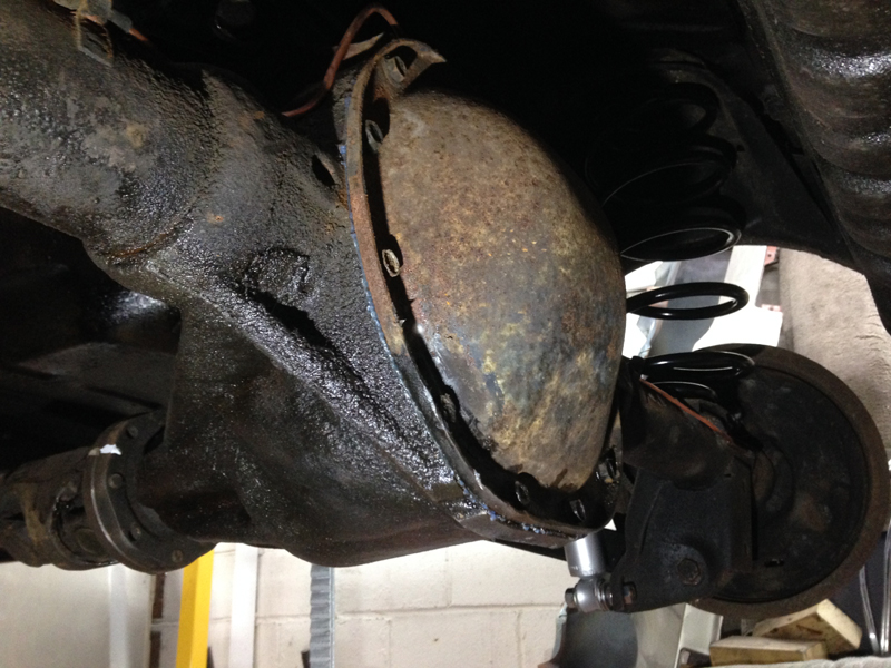
One of the few remaining mechanical jobs that needed doing under the car was the rear axle oil leak. The axle housing was covered in oil and there were signs that someone had attempted to seal the rear cover with some sort of sealer. This would also be a good oppertunaty to drain the oil from the axle and fill it with fresh oil since there is no actual drain plug on the axle housing:
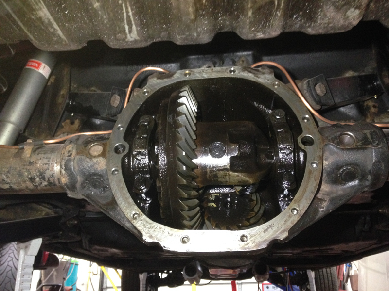
We removed the rear axle cover, cleaned all the old oil out from it, inspected all the gears and cleaned the gasket face ready for the new gasket to go on:
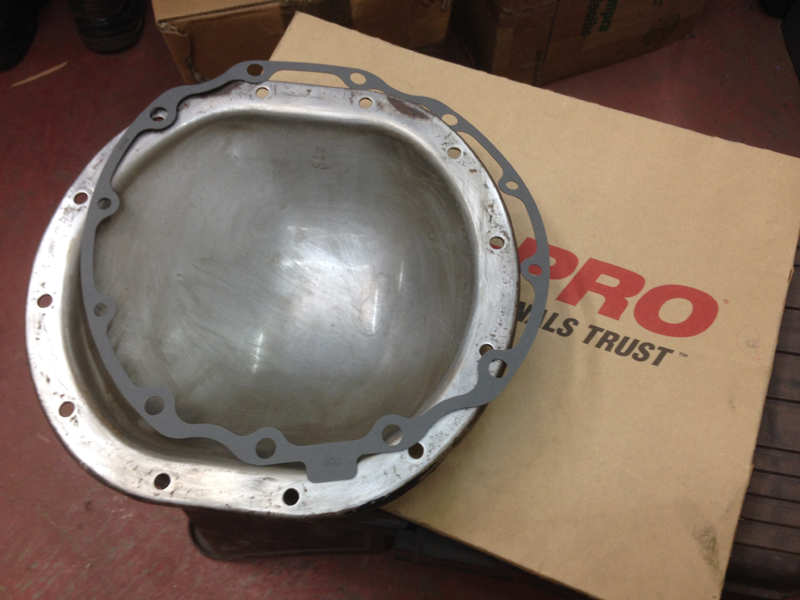
We also cleaned the axle cover itself ready for the new gasket install:
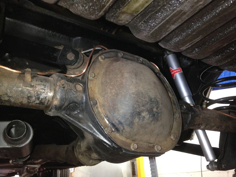
With the cover back in place with the new gasket installed we de-greased the entire axle and filled it with fresh oil:
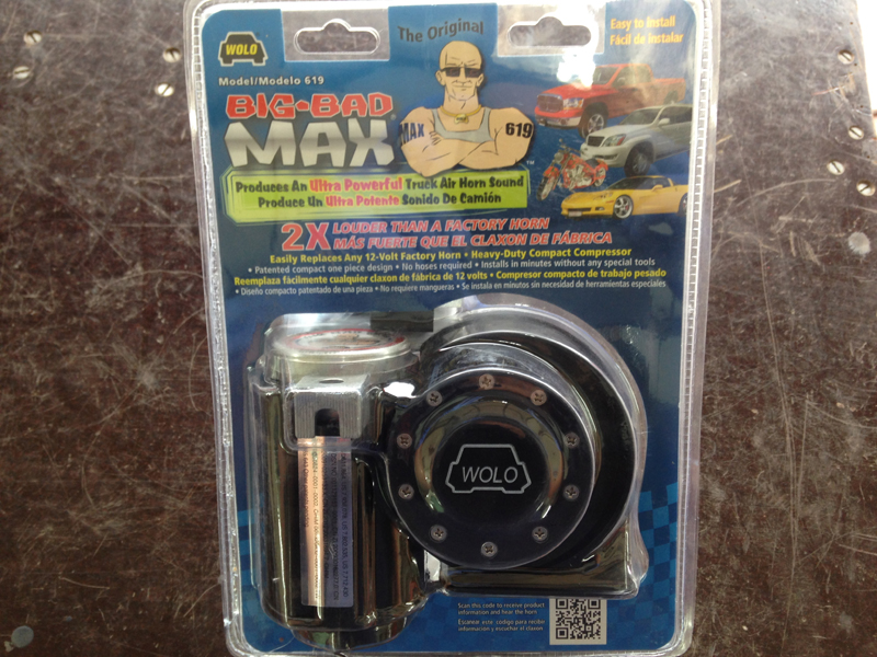
The owner of the vehicle asked us to source a horn that was loud and suited the cars agressive size, unlike the original horn, so we done a bit of research and purchased this horn:
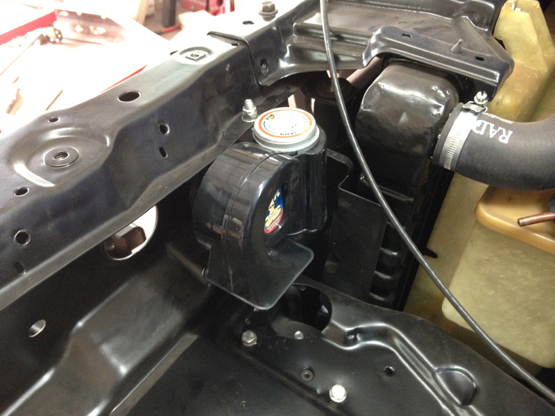
And installed it in place of the original factory horn:
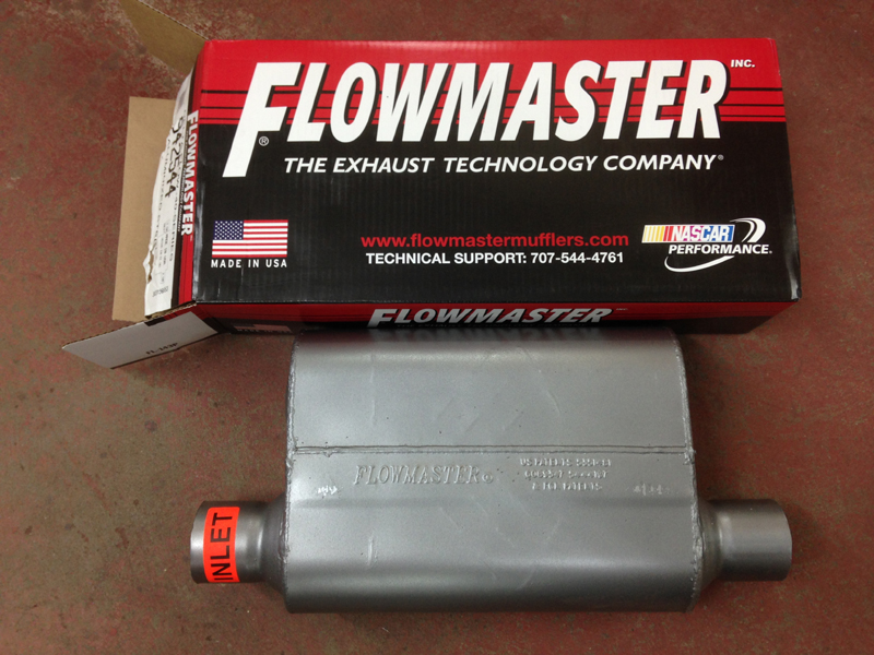
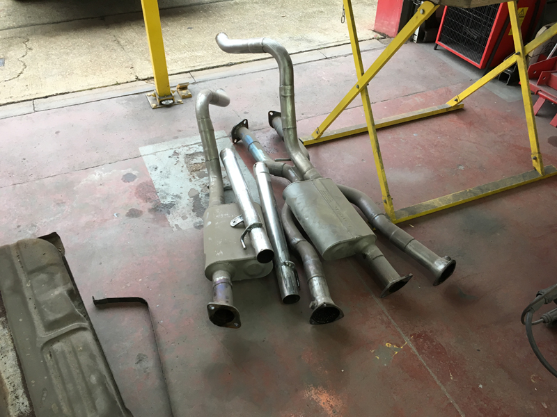
We were waiting for the exhaust silencers to turn up to continue with the exhaust system fabrication, now that they are here we can continue:
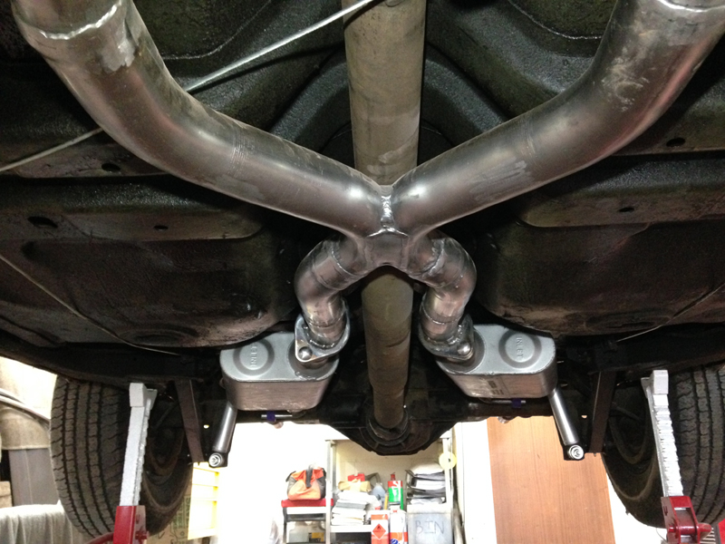
We installed the silencers and made the rest of the system over the axle and out the back of the car and then fabricated hangers to support the system in place:
The finished system with all the hangers and tailpipes. We will have the entire system ceramic coated and all the hanger brackets powder coated:
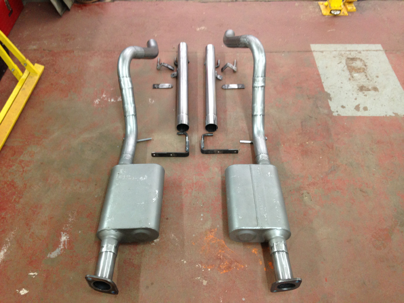
Oval shape exhaust tips chosen by the customer finish the system off nicely:
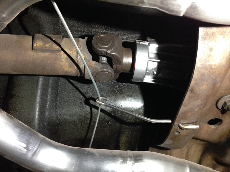
One problem we did notice with the original exhaust system was that the handbrake cable was rubbing on the exhaust pipe on the passenger side:
And that someone had fitted this contraption in the passenger side handbrake cable in an attempt to tighten up a streched cable:
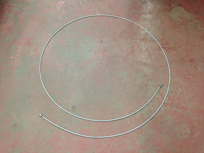
We removed the handbrake cable which was full of kinks like this:
And sourced a new one:
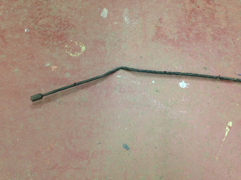
There was still the issue of the cable sitting on the exhaust pipe though due to a missing support bar. The bar itself is not available new and we couldn't find a used one so had to fabricate one. We started with some 6mm steel rod:
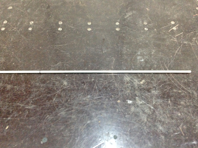
And bent it into shape using diagrams of the original one:
The design works and supports the cable properly allowing it to clear the exhaust and function correctly:
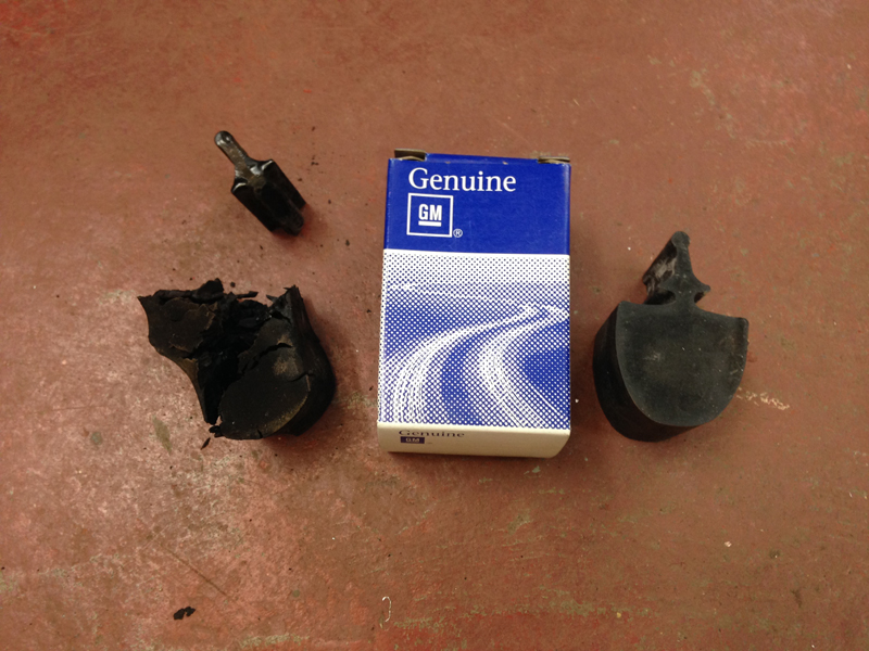
The last suspension part we were waiting for was the front upper bump stops, these finally arrived and we could install them, the originals were far gone:
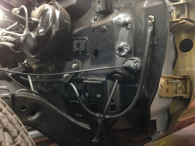
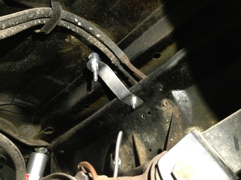
When we built the engine we removed all the emissions and charchol canister set up to install the performance based parts. The fuel tank used to breath through this set up so we had to install a tank breather. We designed and fabricated a bracket to mount the breather to and then mounted it above the rear axle. We still need to connect the hose from the tank and have the bracket powder coated:
With 99% of the cars mechanical side finished we focused on the wiring. When we test ran the engine we had the engine hooked up to a temporary made loom. The cars original engine bay wiring loom wasn't in to bad a shape but some of it did need attention. The first thing we done was install a bus bar out of sight. This allows for several live connections to be made but without having them all straight onto the battery terminals:
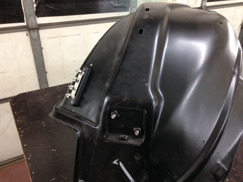
The bus bar does have a cover that we will fit once all the wires are in place. This is mounted at the back of the engine bay low down and can hardly be seen once the car is complete:
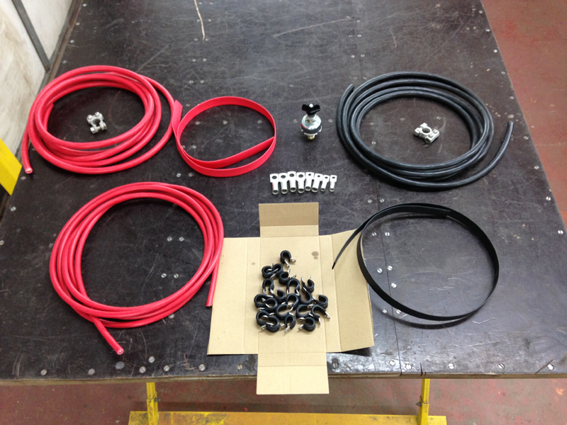
We have always made our own battery cables to our own spec and standards. We will also be fitting a kill switch to cut the vehicles power easily without having to remove the battery terminals:
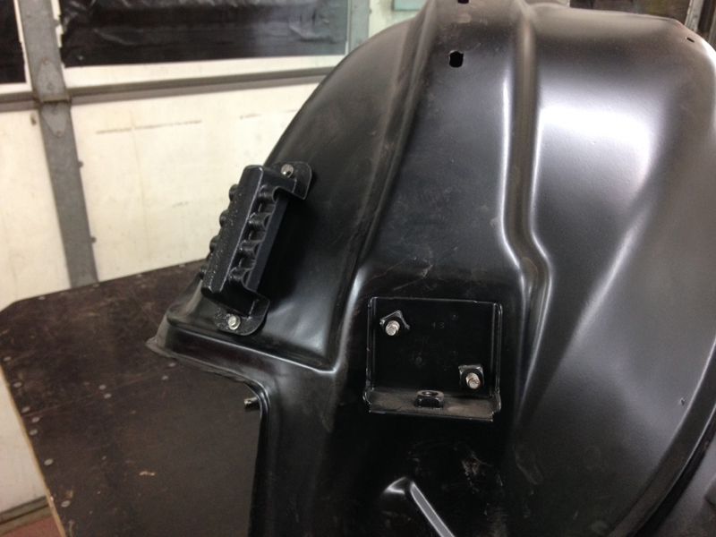
The first step was to fabricate a small bracket to mount the battery kill switch onto and then the battery cables to it. We will get the bracket powder coated to match the inner wing:
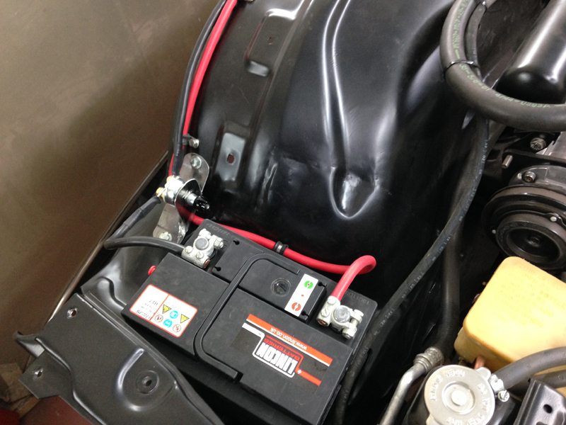
We then routed the battery cables over the top outer edge of the inner wing. Once the wing goes back on the cables will be hidden out of sight behind the wing:
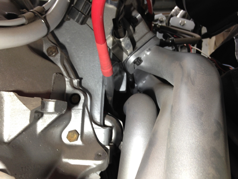
The positive cable then connects onto the bus bar giving a power source for other cables to join onto and the earth cable runs along the lower part of the bulkhead and mounts onto the rear of the engine out of sight:
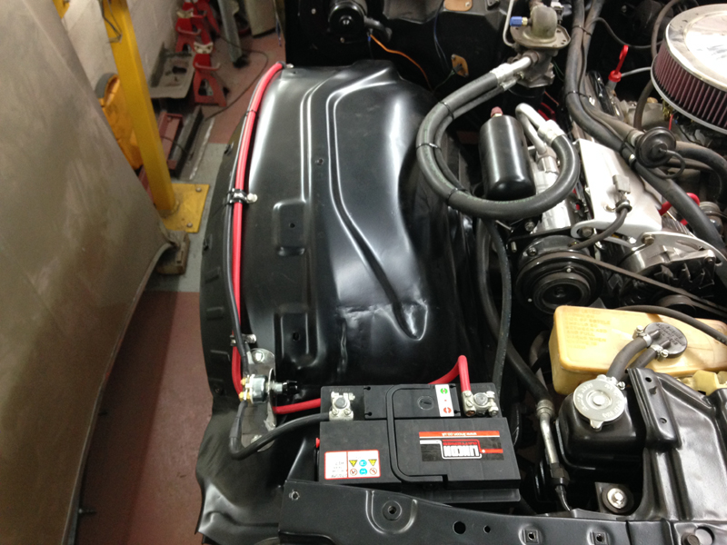
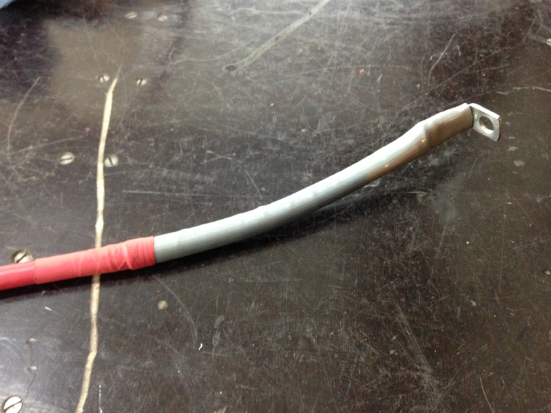
The power cable for the starter motor runs very close to the exhaust manifolds so we installed some heat sleeving on the cable at the point where its close to the exhaust to protect the cable:
Then we installed the cable:
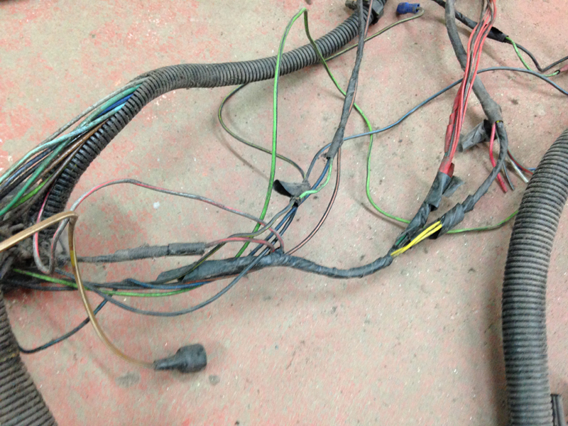
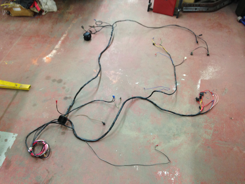
With all the thick battery cables done it was time to take care of the actualy front end wiring loom. This is what we had to start with:
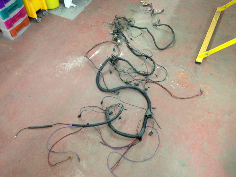
The loom itself was capable of powering the car and only a few wires where completly broken away from eachother but there was alot of previous repairs and wires badly cracked that will have broken over time:
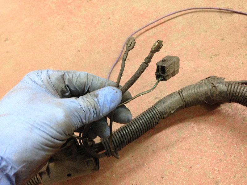
A couple of the connector plugs where damaged and the wires had fallen out of them:
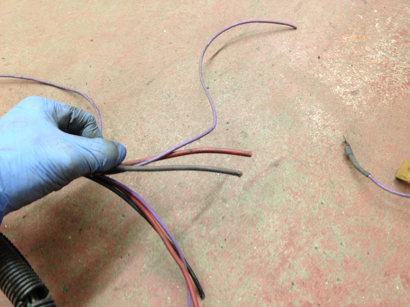
Some wires were taped up hidden in the loom with the ends cut and new wires routed next to them:
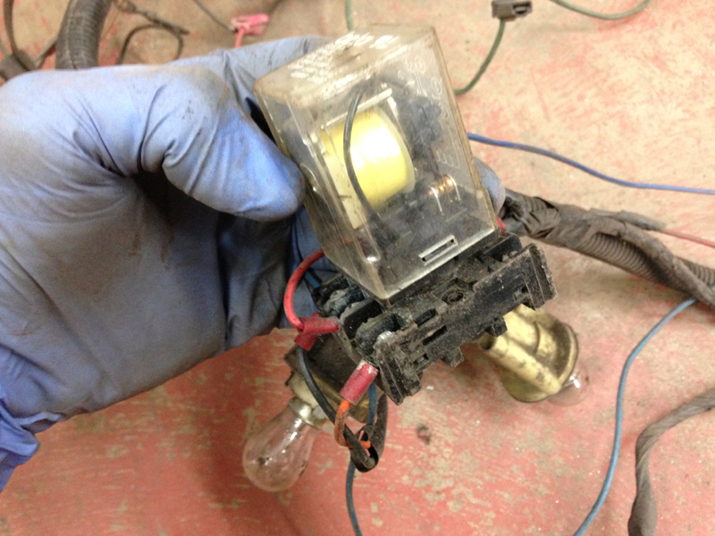
We dont actualty know what this relay was powering as it wasnt connected up to anything anymore except a power supply, so all it did was turn on when turning the ignition on and nothing else:
So after discussing the issues with the owner of the vehicle we thought it best to address the wiring, remove any wires that were no longer needed or damaged and replace them, repair any broken wires that were repairable and fit the correct connectors to things that had the connectors missing:
The wiring for some of the more crucial items, such as the ignition coil and alternator for example, that looked in poor condition was completly replaced from the connector all the way to the item that it powers. This will ensure that the vehicle doesn't have any wiring issues for years to come:
This is the finished front end wiring loom after all the repairs have been made and the loom then insulated:
With the loom finished we installed it back on the car and fitted plastic conduit around the loom:
Then installed the bus bar cover over the bus bar. The factory fuseable link wires were missing so we installed inline fuses at the point of the power supply for those wires to protect the circuits:
Thats the front end of the car wired in completly now:
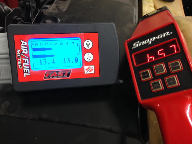
With the car now wired in and now capable of starting of the ignition key, we decided to do some tuning to the engine, first step was to install the lambda sensors in the exhaust system for checking the air to fuel mixture, 1 sensor is installed in either side to monitor both banks seperatly:
Then we started the engine, ran it up to operating temperature and adjusted the ignition timing, idle fuel mixture and engine idle speed:
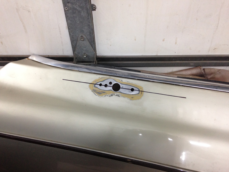
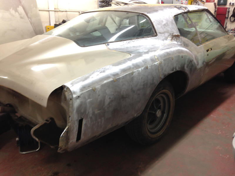
After tuning the engine it was time to get stuck into the bodywork. The plan is to strip the entire car, take care of all the rust and the have it re-painted:
The first step was to remove the vinyl roof and stainless trim around the glass:
And then finish stripping the rest of the trim and bolt on bits from the body:

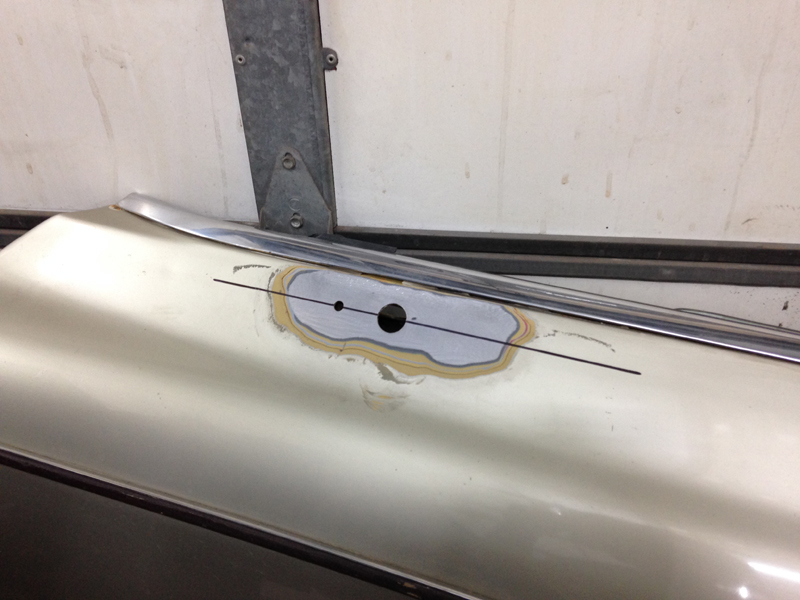
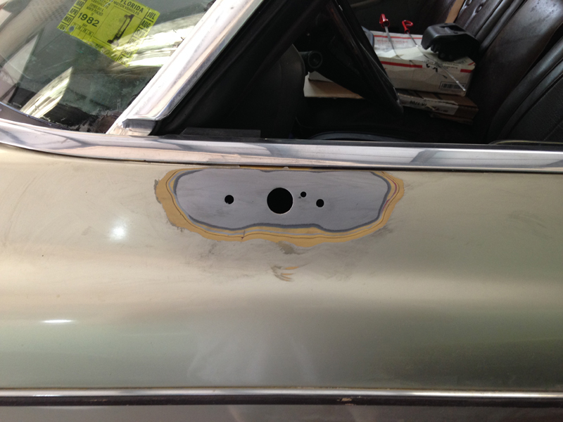
After having a poke about the body in some very suspect looking places, it was quite clear that the car was going to need alot of work to get the body right. This is the join through the C pillar where the roof meets the quarter panel:
So a decesision was made with the customer to bare metal the car completly, find all the rust issues and address every one of them:
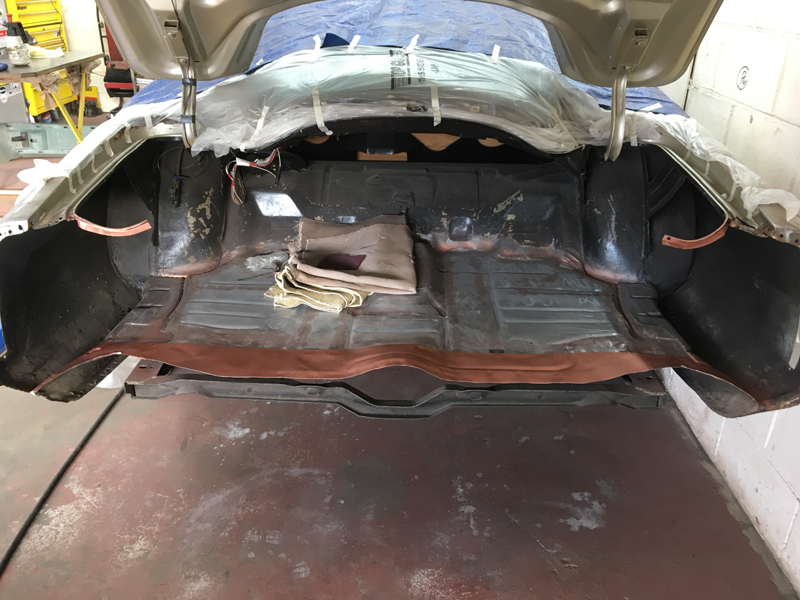
This is the boot floor, from this picture it looks pretty solid but from underneath there was evidence of some very poor rust repairs and alot of sealer hiding things. A replacement boot floor was available so we decided to replace the entire panel:
The first thing we had to do was remove the exhaust, we plan on having the entire system ceramic coated anyway so it was due to come off:
Next we removed the fuel tank:
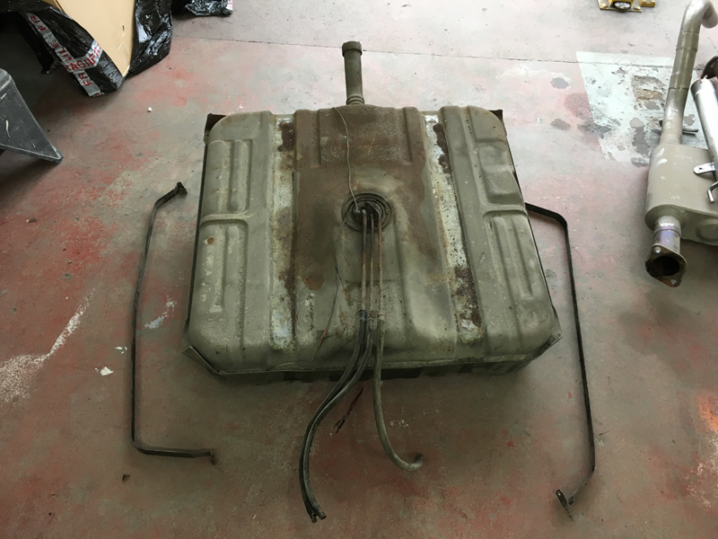
This left us with plenty of access under neath and without any risk of damaging any items under the car:
This is the replacement boot floor panel that is available of the shelf:
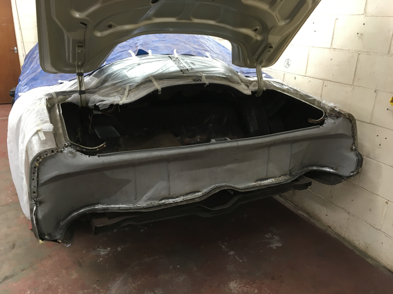
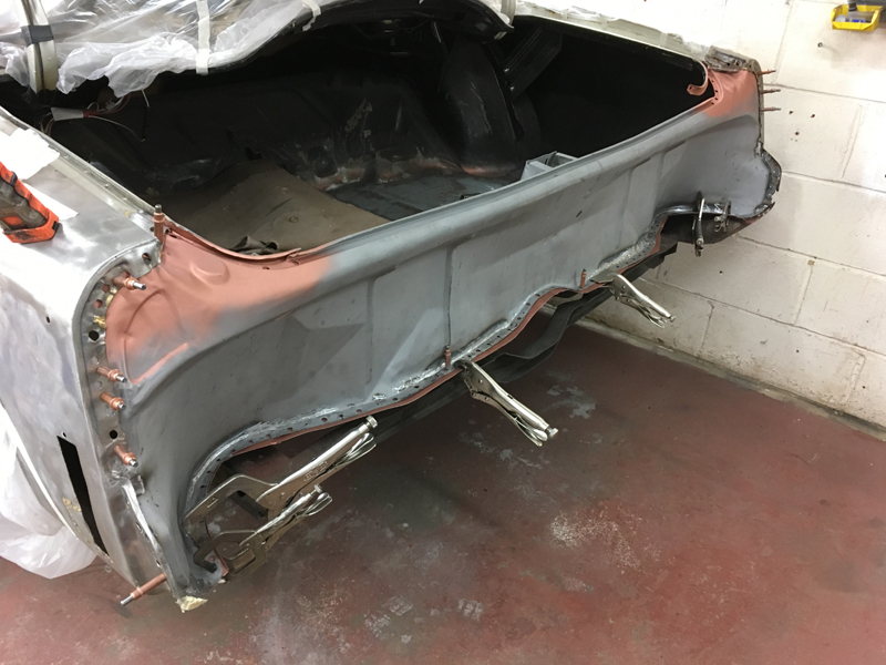
Unfortunatly to get the entire old floor out we must first remove the rear panel from the body as the floor is sandwhiched between the panel and the rear body crossmember, this also does us a favour as the rear panel has some rust issues that need taking care of:
We drilled all the factory spot welds and had to cut through some poor previous rust repairs and this let us remove the panel:
We tried the replacement boot floor into the car to see how it fitted, unfortunatly like most replacement panels the fit was very poor and would need some attention to make it fit:
Step 1 was to trim the panel to size for how we wanted it in. Then we could address this area, we have no idea why but this is how the panel came, we are not sure if it was just cut wrong at the manufacturer or if it fits another vehicle that needs access at this point, either way, the area needs filling in for this aplication:
We cut a section of steel to shape and clamped it into place:
And then welded it in fully:
Then ground the welds down:
We also had to reshape the rear middle section of the panel so that it has the raised hump in it to match the crossmember for where it goes above the fuel filler neck. We could then pin the panel into place and mark out where we wanted to cut the original boot floor out:
The arrows are where the spot welds are that secure the floor to the vehicles crossmember, these must all be drilled out and the line is our cut line:
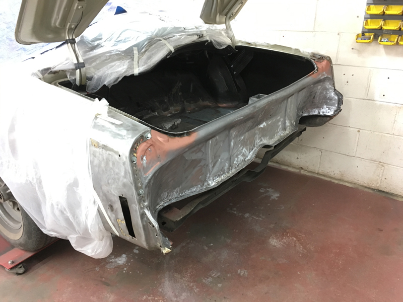
After a bit of cutting and drilling the old boot floor is out the way:
With the old floor out the way we pinned the new floor back into place and marked out where the crossmemers where and then drilled the holes in the new panel where we would plug weld it into place:
After the holes were drilled and we were happy with the fit of the panel, we prepped the underside of it for paint:
Then applied the etch primer:
Followed by the red anti-rust primer:
Finally followed by the weld through primer on all the areas that the welder will be used:
Before we could weld the new boot floor in we had a few more issues with the car body to address:
First we bare metaled all the edges of the remains of the old boot floor so that we could weld the new one in place:
Here is one of the previous rust repairs, poor welding that is not continuous around the repair and the repair has just been welded on top of the rust hole rather than cut the rust out which is why the rust has contined to spread even after the plate was welding in. We have said it time and time again, but the only was to stop rust from spreading is to competly cut it out, there is no other way and no holding it back:
Again more poor previous repairs here:
And on the other side in the same spot:
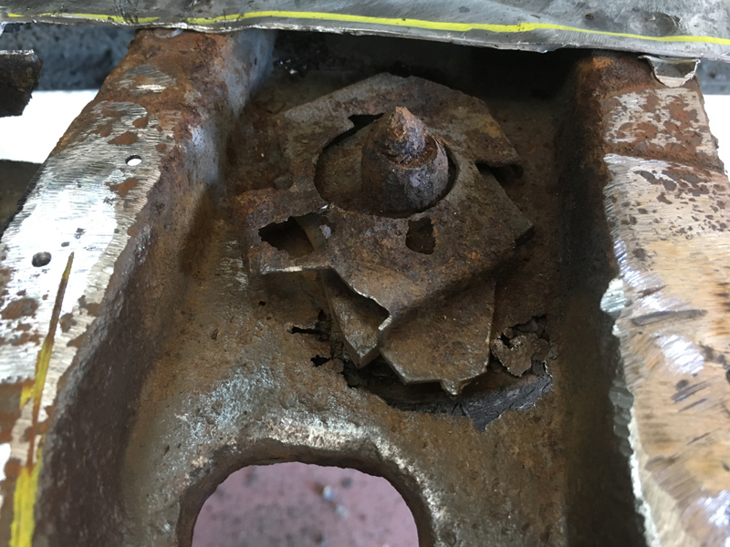
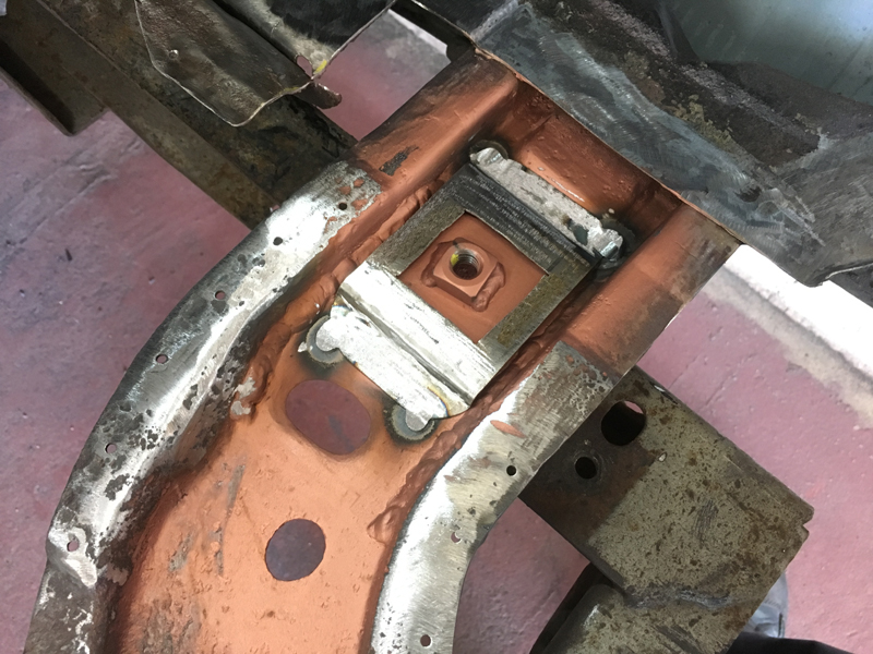
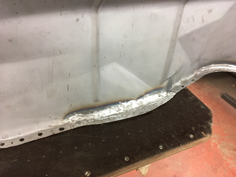
The real issue that needed addressing was the rear body mounting points:
You can see on the top section evidence of previous repairs to the boot floor where plates were just welded on top of rust holes to hide the rust and also on the lower section where the body sits on the rubber mount, rust has eaten away at this area completly, if left the body mount would just come through the body leaving the body no longer bolted to the chassis at the point on the vehicle:
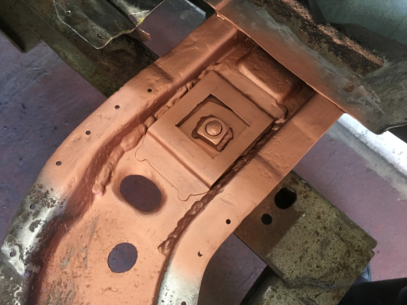
First we ground out all the surface rust and dirt from the crossmembers to reveal the solid metal. Even though the metal is has a brown tinge to it, its not rusted or rotted out, this metal is solid and just needs a quick bit of treating before painting:
Next we marked out all the areas that needed attention and repairs:
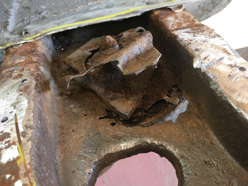
We addressed the passenger rear body mounting location first and cut away the top section above it:
Showing the extent of the rust and the broken cage nut that is designed to stop the captive nut from spinning when unbolting the body:
First we removed the bolt that runs through this mount and then got the mount out the way, this body mount just like all the rest is completly worn and will need replacing. We will replace all the body mounts on the vehicles once the structures have been repaired:
Next cut of the cage nut assembly and ground out all the rust and rotted steel to access the extent of the damage:
Then cut out the rusted out section:
Then fabricated a repair section to go in its place:
And then welded it in. We ground the welds on the left and right side of the repair so that the weld doesn't act a damm and stop rain water draining out the sides like it is meant to:
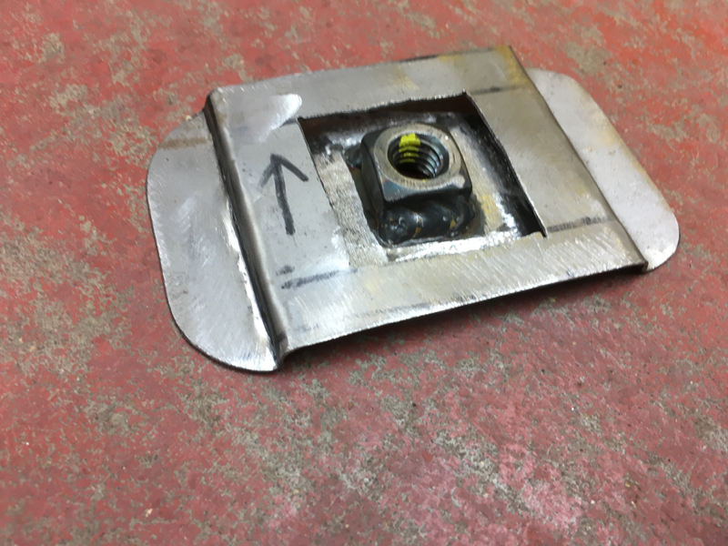
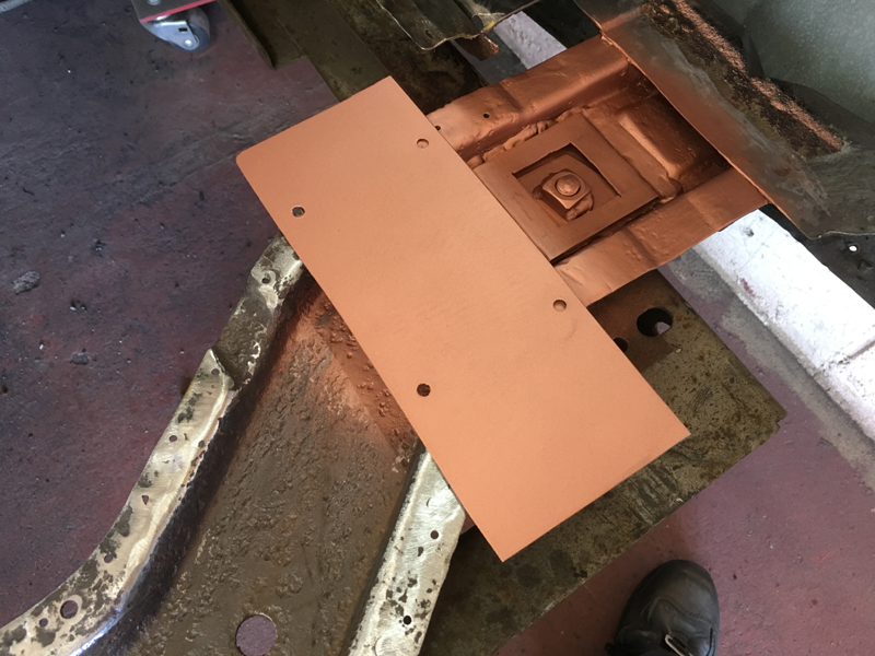
Since new cage nut assemblies are not available we had to fabriacte one. We started by welding a square nut onto a thick plate cut to a diamond shape and the made a cover to go over it:
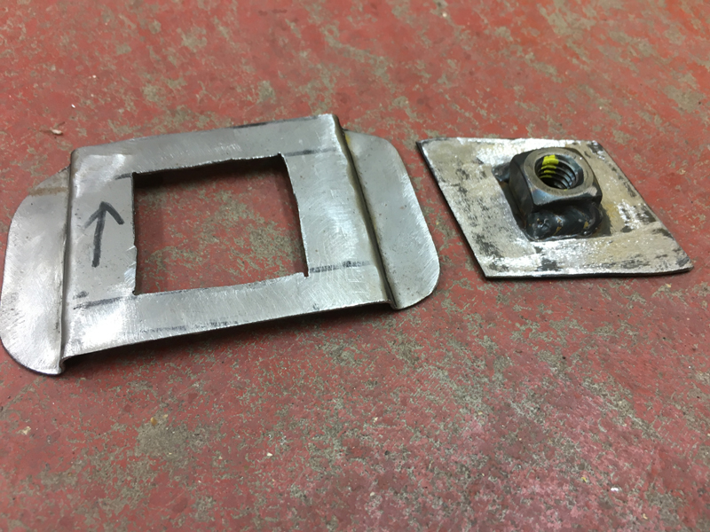
When the cover is over it, the diamond shaped plate can turn a small amount and move a small amount to help with aligning body back onto the chassis and getting the bolt back in the hole, but the cover doesn't let the plate spin completly so that you can tighten the bolt up:
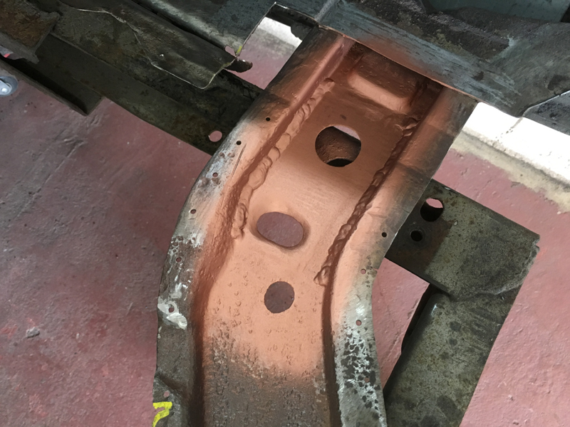
We painted the area where the cage nut will go in weld through primer:
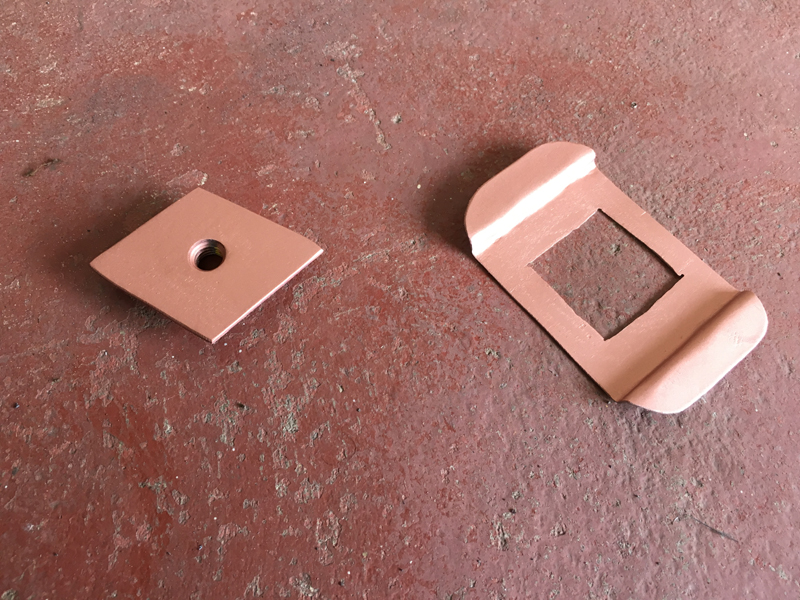
The painted both parts of the cage nut assembly the same way:
Then welded the assembly into place:
The painted the area in weld through primer:
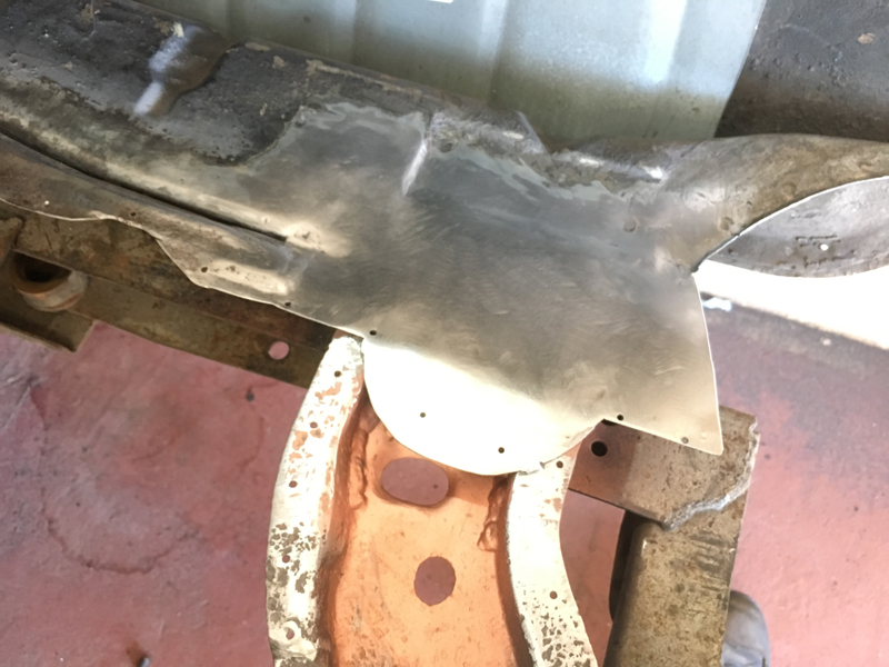
Next we began fabricating a new cover to go over the cage nut:
And after painting the underside in weld through primer, welded the repair section into place and ground the welds:
The driver's side of the vehicle needed the same repair in the same spot:
We repaired the body mounting point in the crossmember:
Fabricated another cage nut and welded it into place:
Then fabricated a new top section and painted it in weld through primer:
Then welded it into place:
We then moved on to the next repair and cut out the previous poor repair completly:
Cleaned up the area and painted it in weld through primer:
Fabricated a repair section and painted that in weld through primer:
Then welded it into place and ground the welds down:
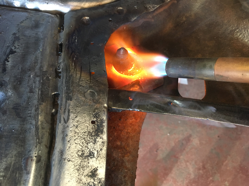
There are 4 body mounts in the boot area of the car. The rear 2 of the 4 are what we showed above. The front 2 didn't need any rust work but we wanted to make sure we could get the bolts out while we had access to the cage nuts incase the bolts snapped. Both were siezed so we applied some heat and got the bolts out without them snapping:
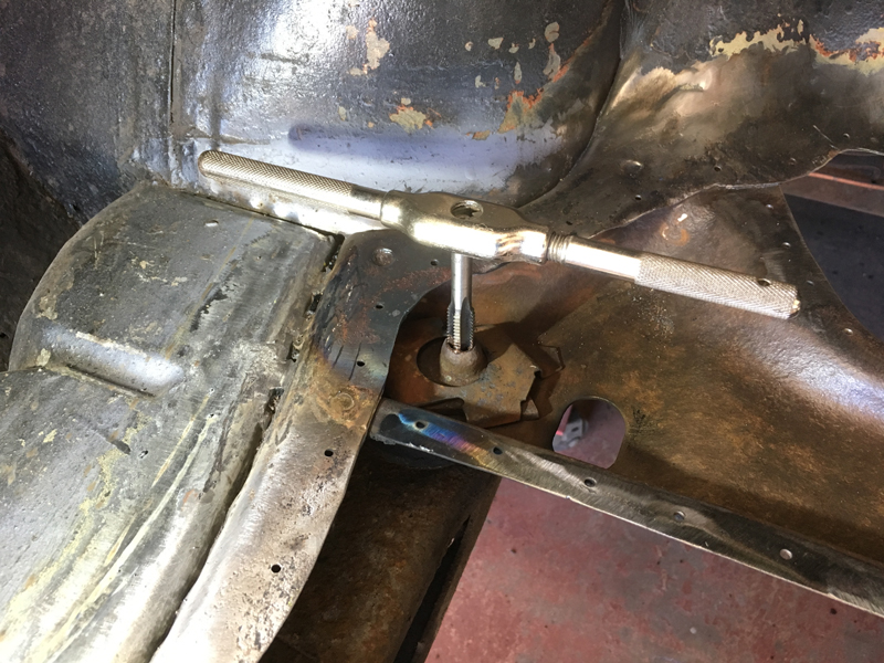
Then ran a tap through the threads to clean them up so that they can be used again:
This is one of the body mount bolts that we managed to get out without snapping. This is the reason we will be replacing all the body mounting bolts on the car because even though the bolt didn't snap, the bolt has started to rust away and has become weaker because of this:
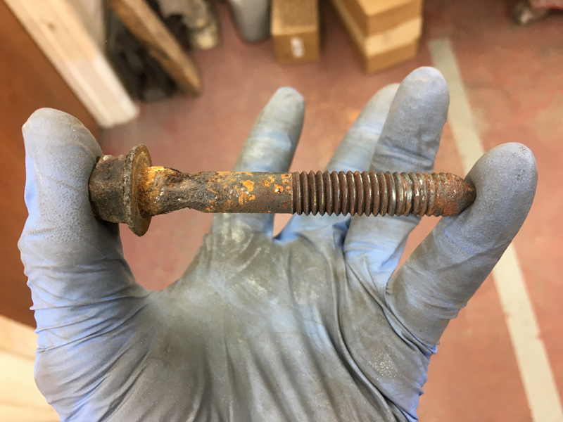
We ordered some new high tensile strengh bolts which we will use in all the body mounting locations:
With the repairs to the boot floor area of the car now complete, we bolted the body back down to the chassis in all 4 points using the old mounts for now so that we can move on to the next step:
We treated the surface rusted crossmembers with a rust treatment product to convert the surface rust back to good steel:
This will prevent this from going rusty again for the forseable furture:
We then applied the etch primer to all the crossmembers on the rear that will be covered by the boot floor:
Followed by the anti-rust paint on top of it:
Finally followed by the weld through primer on the edges and areas to be welded:
We then pinned and screwed the new boot floor panel into place:
We do this so that the panel is pulled nice and tight to the body crossmembers which makes it stronger:
The screws are all spaced roughly 1 inch appart and and will be removed 1 at a time then plug welded for strength:
With everything set and good to go, we welded the new boot floor into place:
Then ground the welds down. The boot floor is now strong and safe and with all the internal box sections painted will keep the rust at bay for many years to come even in the poorest of weather conditions:
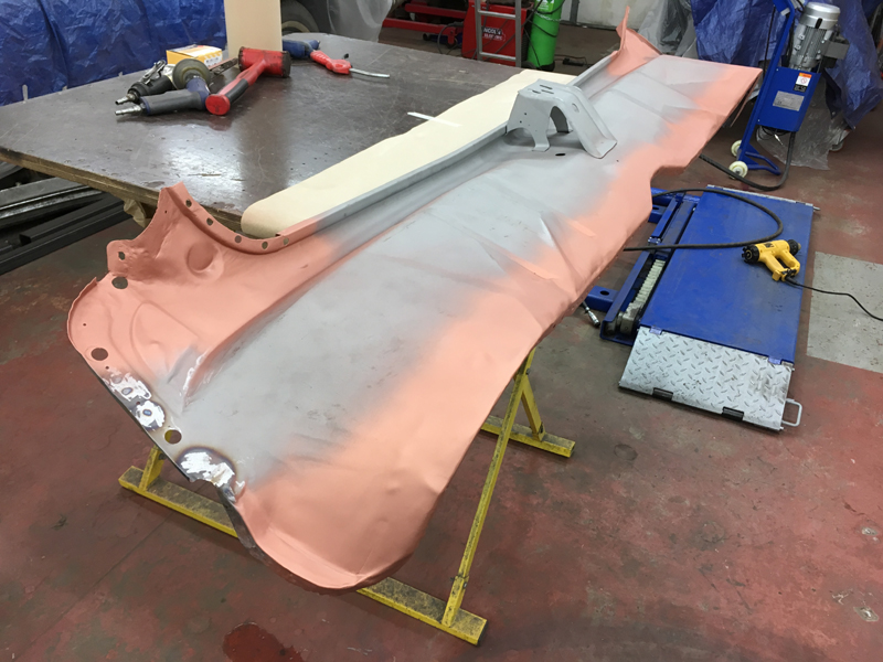
With the boot floor completed we could concentrate on repairing the rear panel and getting it fitted back onto the car:
First we had the panel sand blasted to remove all the rust and remains of the old paint that was in the awkward shapes that would have taken for ever by hand:
Once the panel had been blasted we could see all the areas that would require attention to them:
We started by cutting out the rusted areas a section at a time:
And then fabricated a repair section for each area which we welded into place and then ground the welds flush:
With the rear panel repaired we could start trial fitting the panel back into place:
Once we were happy with the fit of the panel we painted the areas where the rear panel meets the rest of the car in weld through primer:
And did the same for the rear panel itself:
Once the paint was dry we began clamping a clipping the rear back back onto the car:
Once 100% happy with the fit, we welded the panel into place and ground the welds:
Now the owner can safely put items in his boot compartment without fear of them falling out and also the car is just as strong as the day it was built:
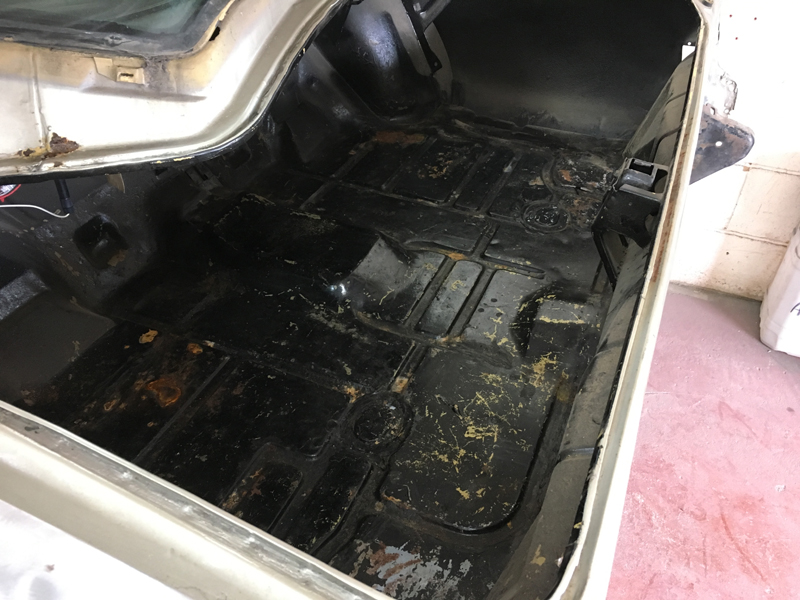
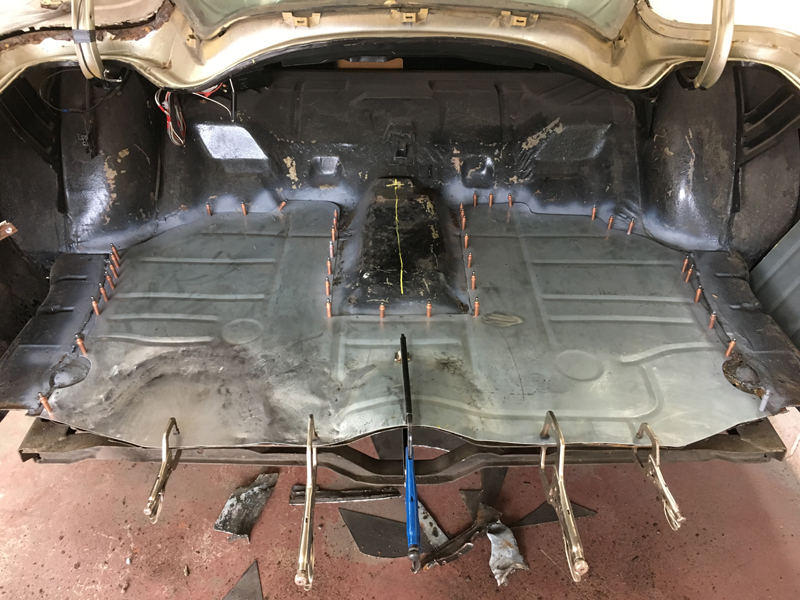
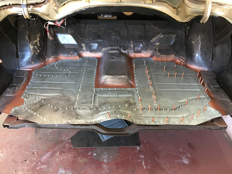
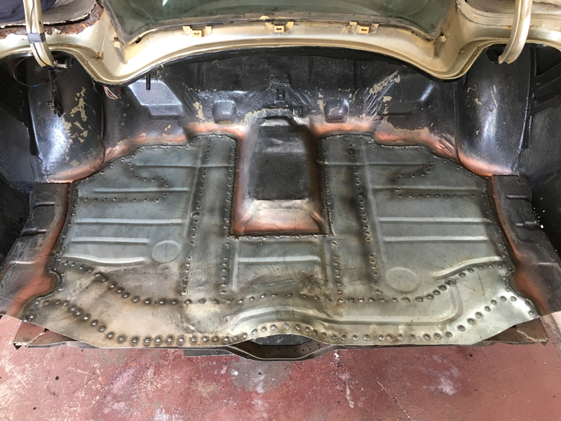
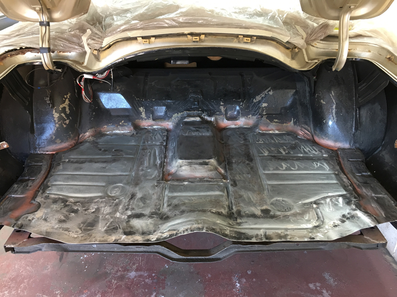
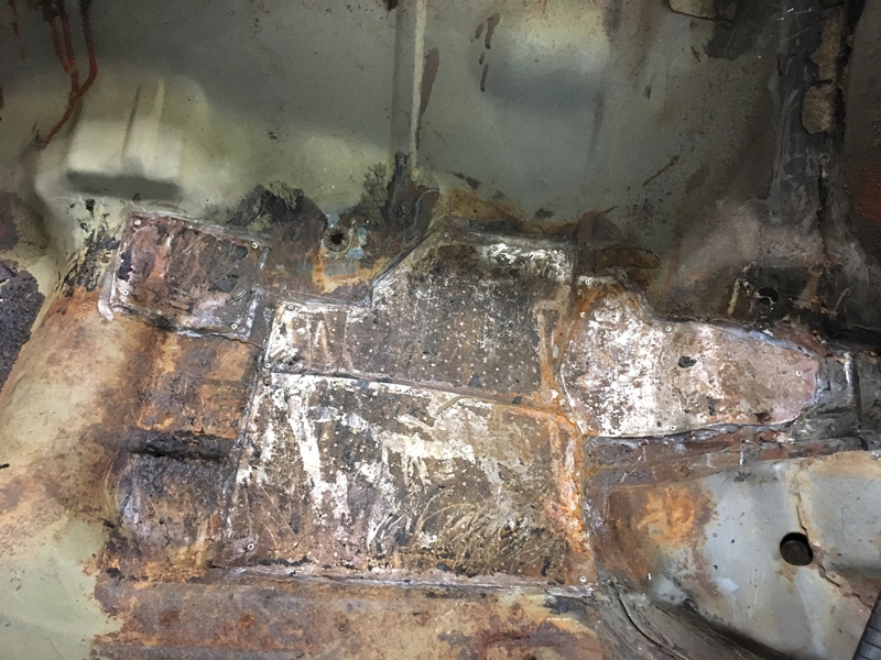
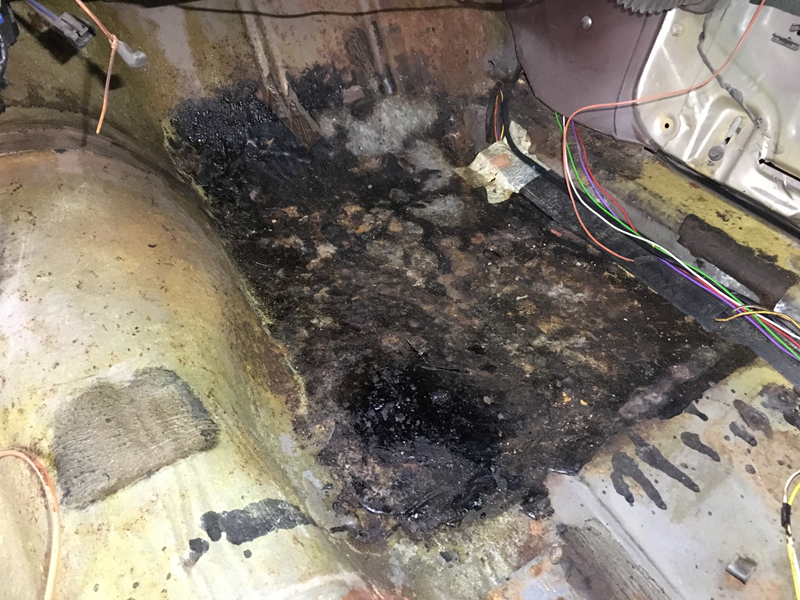
With the back end of the car finished as much as possible for now we moved on to tackling the floor pans inside the car. When we pulled the carpet out we found someone had put tar and a couple of sound deadening pads over odd areas of the floor pans. When we removed these we found some poorly made repair plates that were fixed to the car with a small number of rivets and sealer:
The same thing continued with throughout the floor pans in various places:
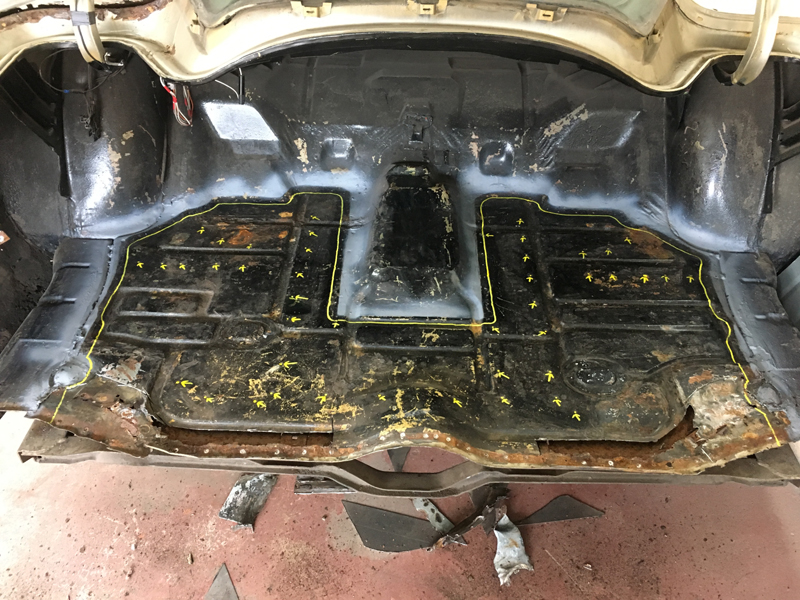
When we drilled out the rivets the repair plates easily just lifted away to reveal several rust holes:
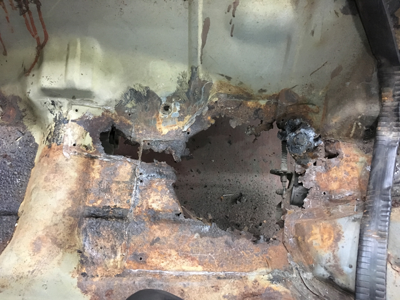
This is the passenger front floor pan, it has completly been covered with a brush on tar that has been melted to the floor pan to hide a poor repair:
Before we started cutting out the floors we wanted to brace the body shell, this wasn't just for replacing the floor but we would also be removing the quarter panels and the roof skin at some point so we thought we may as well brace it now to keep the shell as square as possible:
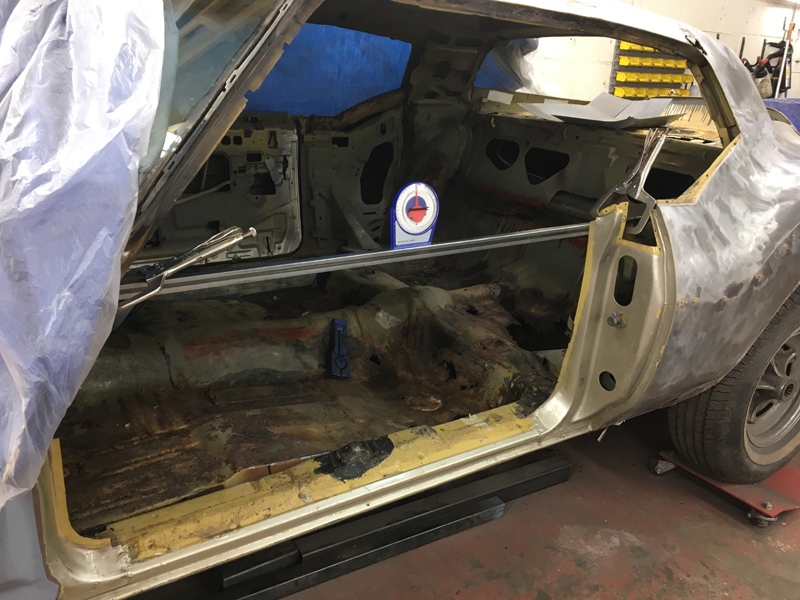
We braced the shell accross the door shuts and then between the B pillars and then down to the transmission tunnel:
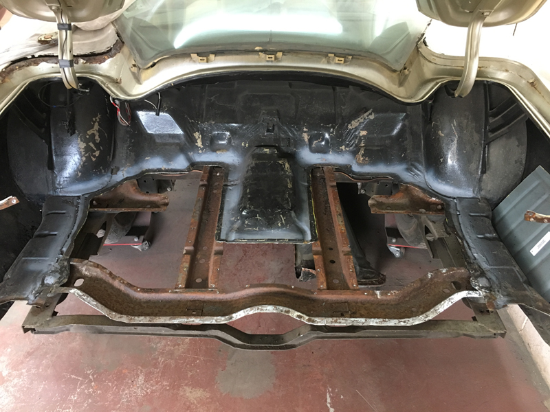
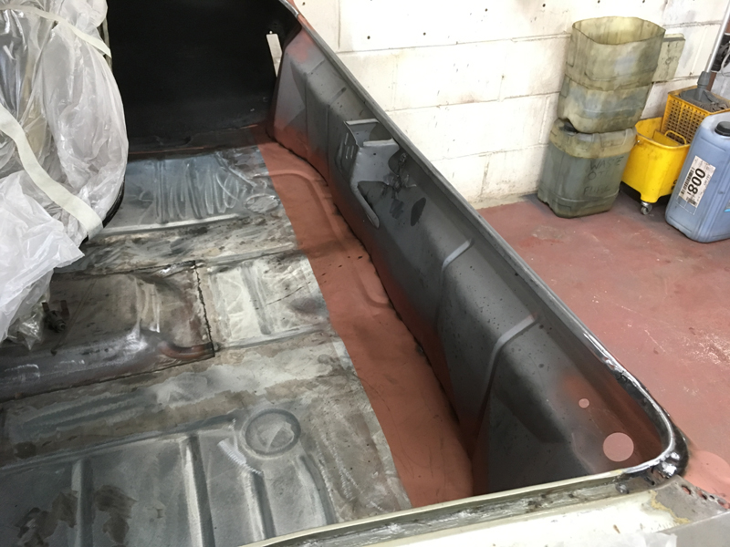
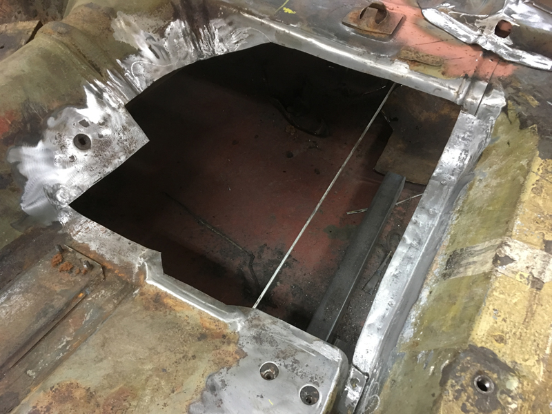
With the bracing complete we cut out the remains of the rust on the driver's rear floor pan that is under the rear seat. We also had to cut out a section of the body side support brace to get access to the floor pan properly:
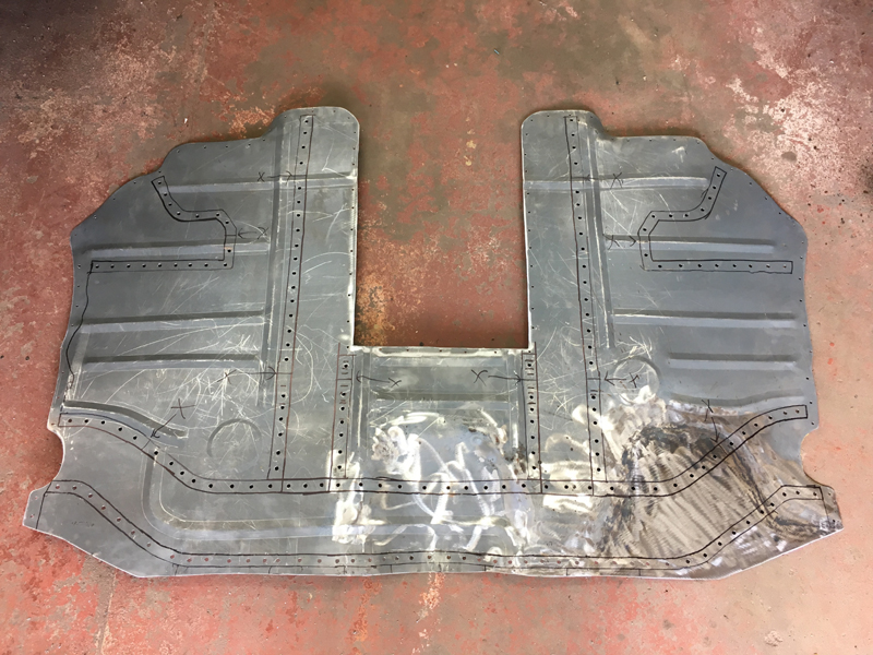
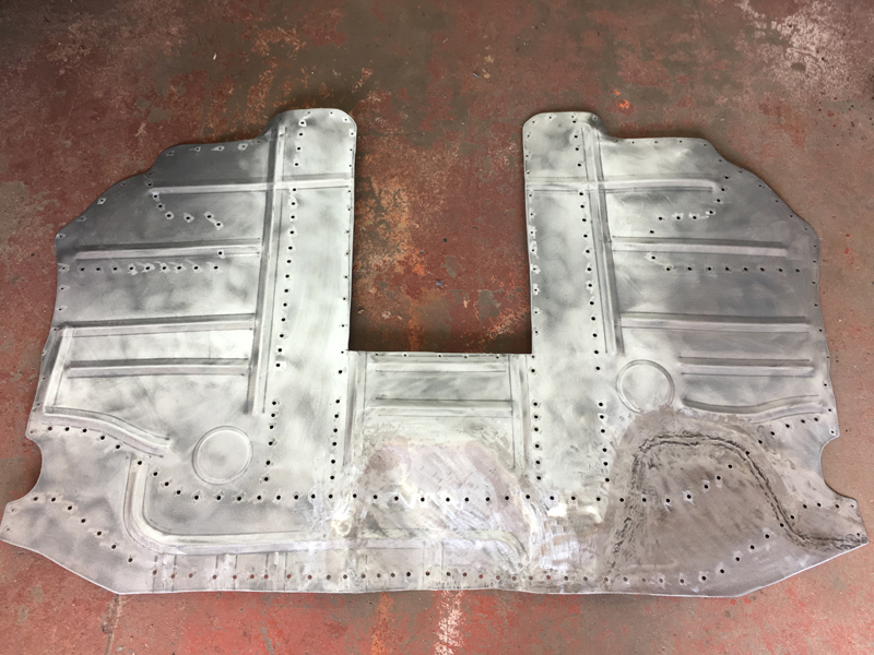
There is only 1 company that produce floor pans for these cars, unfortunatly the fit isn't very good and unfortunatly this car is so rusted that the floor pan wasn't large enough to cover the entire rusted out area:
We had to fabricate an extra piece of the floor pan before we could weld the repair panel into place:
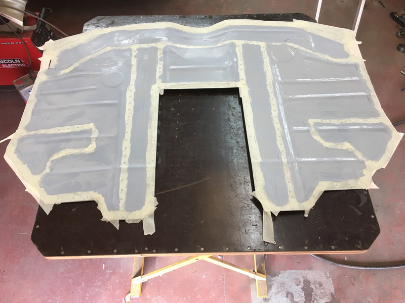
With the new floor in place we painted some weld through primer onto the new floor where the body support goes:
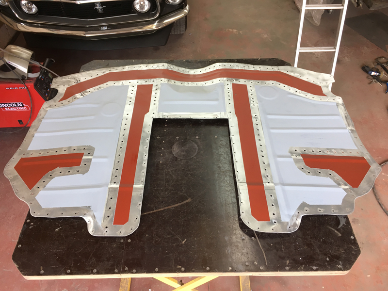
Then welded the body support back into place and ground the welds on it:
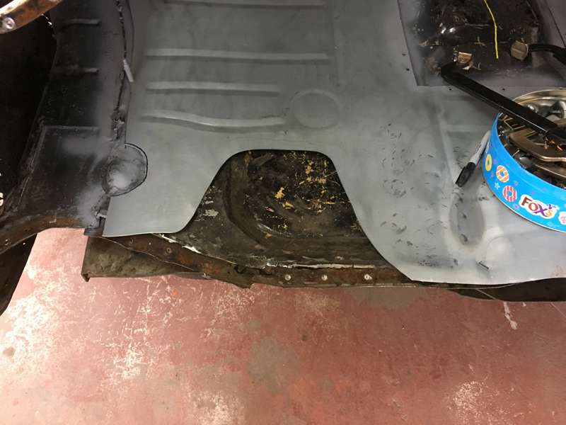
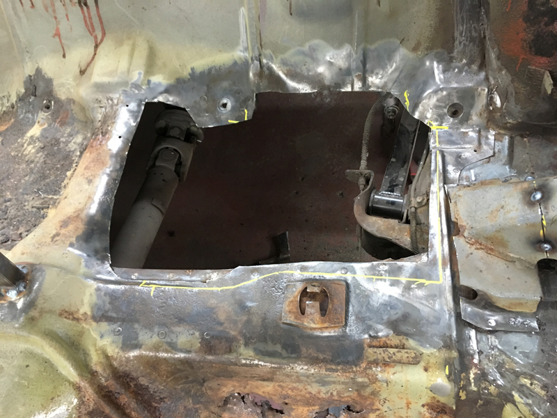
Then we moved forward onto the driver's rear footwell floor pan, this also had rust holes in it and was generally very thin all over:
We marked out where to cut and the cut out the old floor pan:
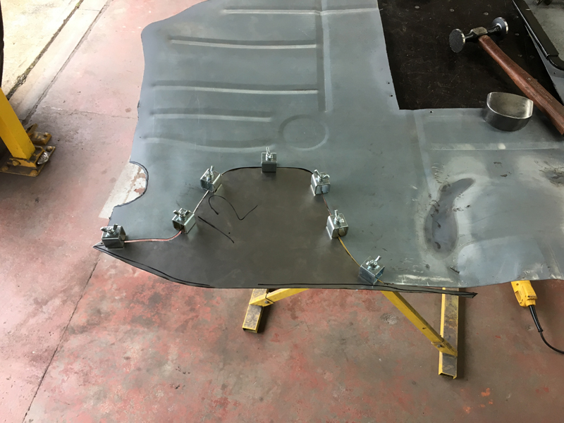
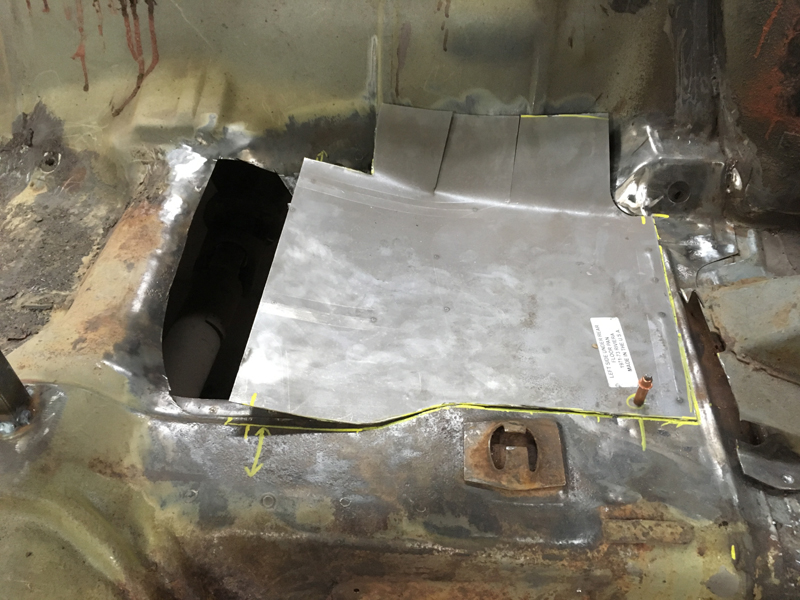
We trial fitted the new floor pan into place and it was clear that this area would need a small section fabricating to fill the gap:
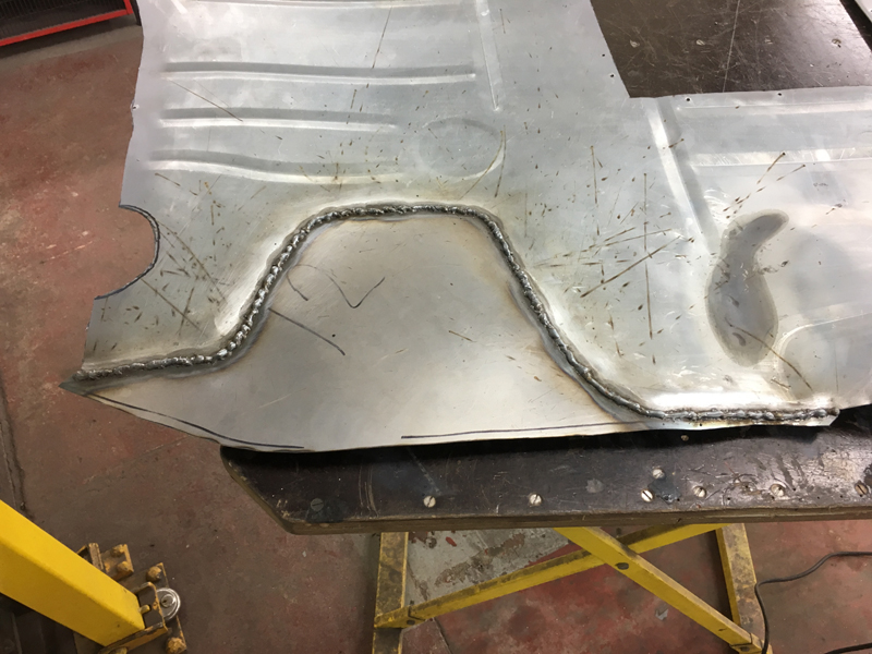
With the gap filled and the floor ready to fit we cleaned up the area where the floor pan will weld to:
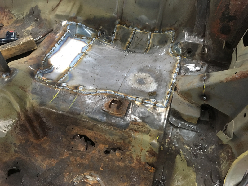
Then painted weld through primer on the overlapping areas of the original floor and the new floor:
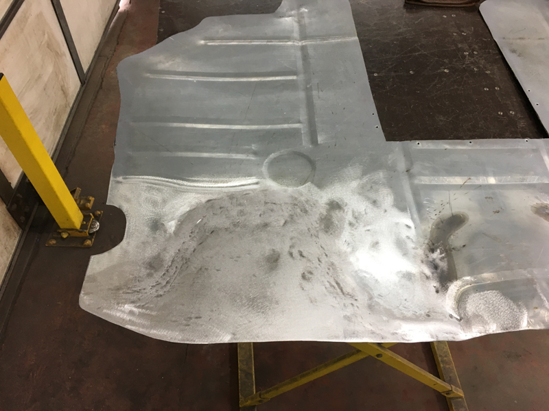
Then welded the floor pan into place:
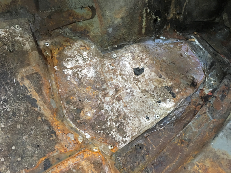
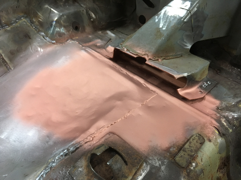
Next up was the driver's front floor pan, there were a few rust holes in it but not as bad as the rear pans but the floor was heavily pitted all over with cracks in the areas where it was very thin so we thought it best to replace the entire floor pan here too:
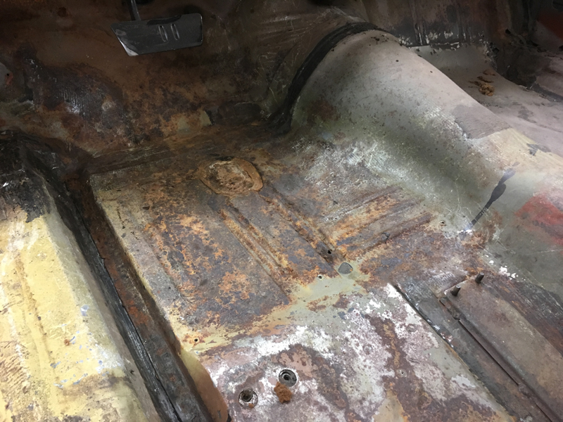
We cut out the original floor pan and cleaned up the surrounding areas so the new pan could be welded in:
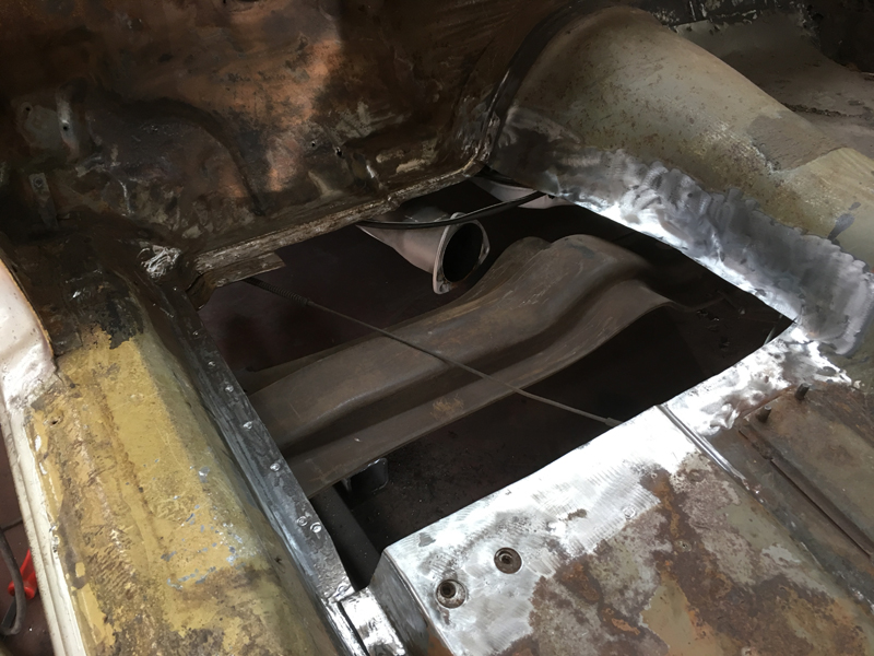
The front floor pan fit wasn't as bad as the rears. We had to adjust the shape of it in several places but at least we didn't have to add any metal or cut any away or re-fabricate it. Once we had the fit correct we painted the overlapping areas in weld through primer:
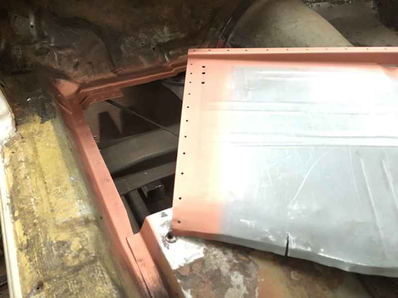
With the floor pan welded in we had to sort out a few rust holes in the driver's toe board:
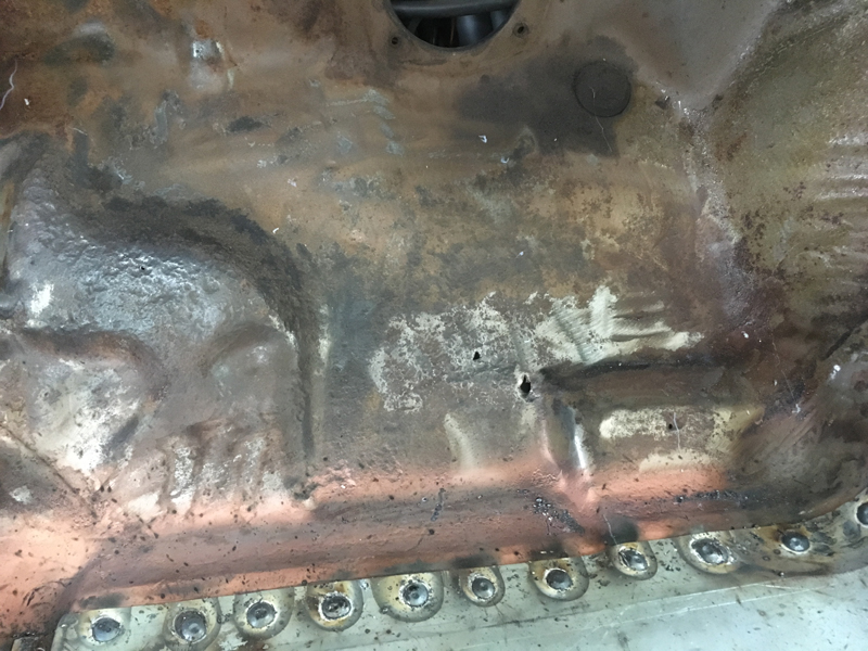
Since the holes where just small areas we just drilled the rust out:
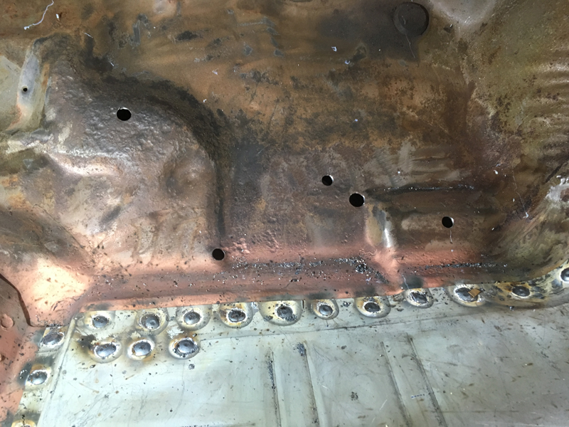
Then welded small repair plates over the holes to seal them up:
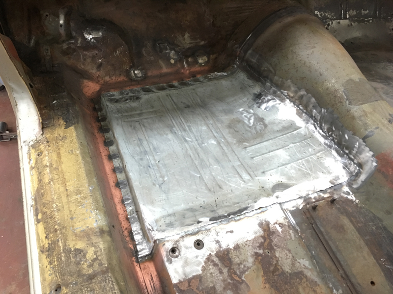
All that was left to do on the floors on the driver's side was fabricate new wiring loom retaining tabs for the ones that had rusted away and broken off:
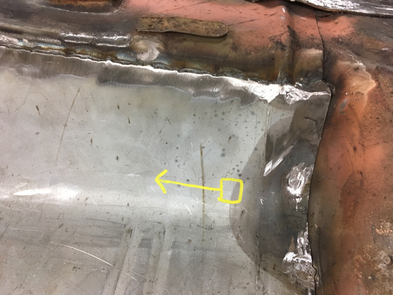
Then weld them into place just like the originals:
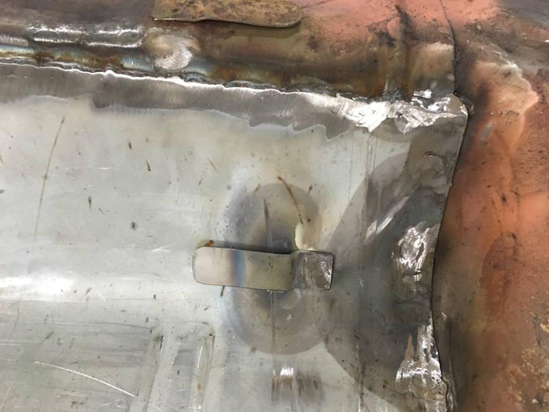
On the left is our floor pan repair. On the right is someone elses previous attempt. We know which one we would prefer to have in our own vehicles:

One thing we noticed when taking the interior out of the car was that there was quite a bit of play in the steering column. One the car was stripped we discovered why. The studs that the column mounts to the car with were no longer welded to the car:
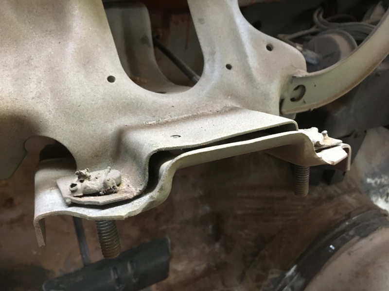
This meant that the nuts that go on these studs couldn't be tightend up and were just spinning round when whoever installed the steering column last attempted to tighten it:
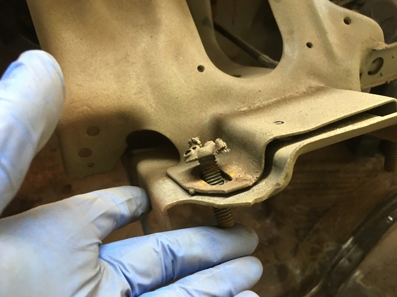
We cleaned up the heads of the studs and their mounting points and then welded them back into place. At least now the steering column can be fitted correcrtly when the car goes back together:
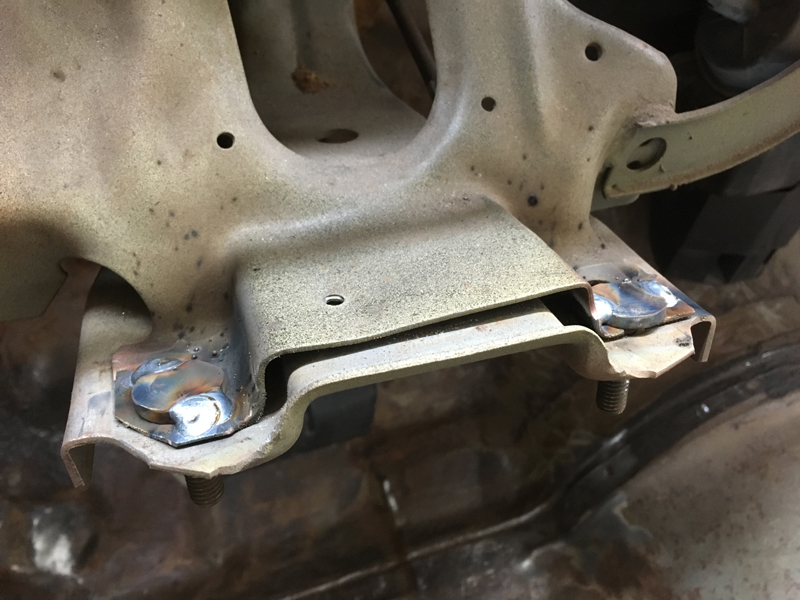
With the floor pan work on the driver's side of the car complete we decided to stay with the driver's side of the car and tackle the quarter panel repairs. The entire panel was a mess (though not as bad as the passenger side one) and needed repairs all over:
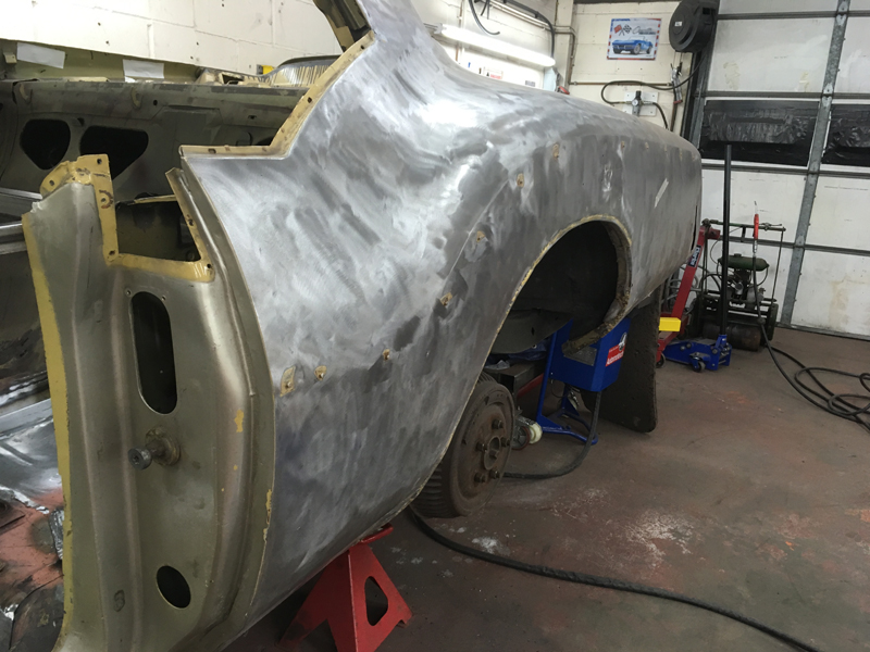
The owner of the vehicle had decided against fitting the factory side moulding back on so it looks smoother like the earlier cars, we may go with a pinstripe down the side of the car to simulate the moulding once its painted but will decided on that once the car is painted, but for now we just needed to get rid of the welded on studs that the trim mounts too:
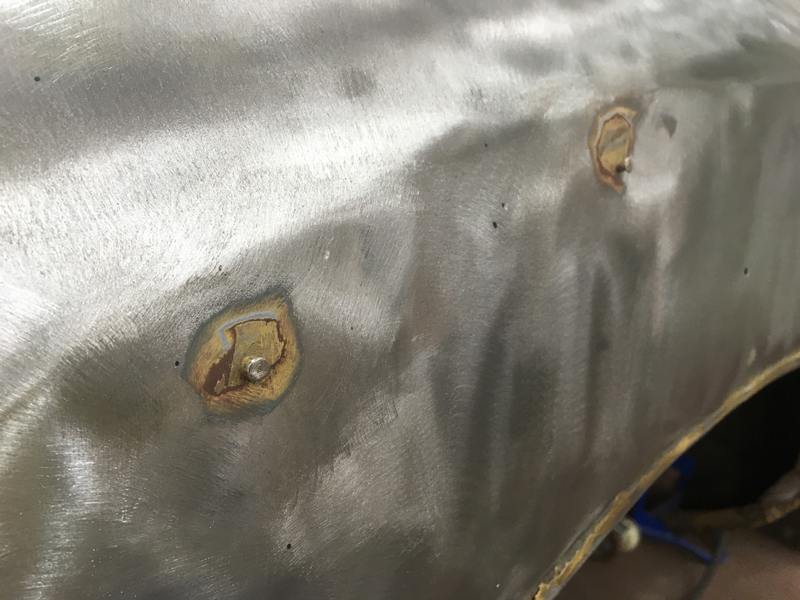
So we ground all the studs down flush with the rest of the metal work:
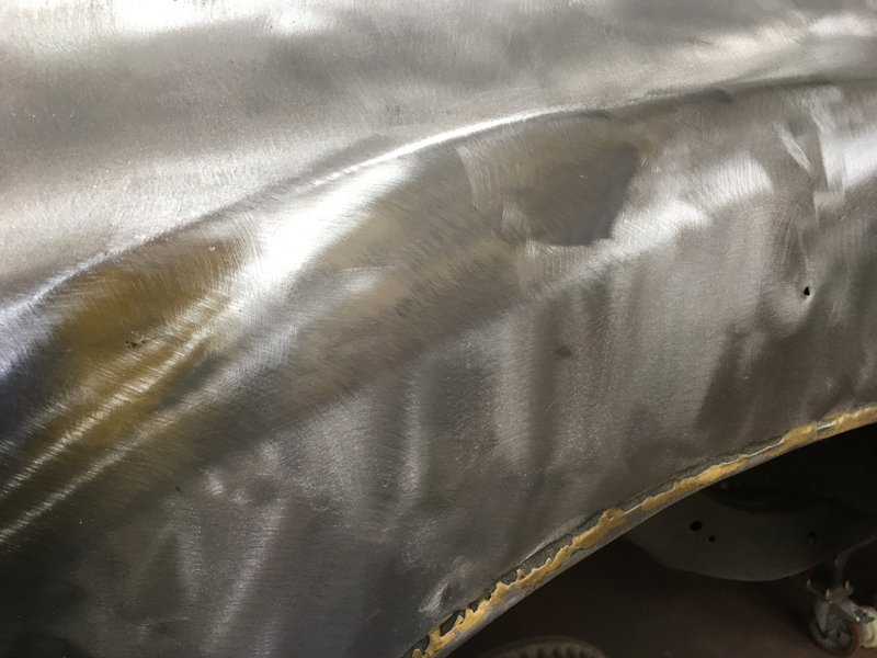
Then had to make a start on the rust repairs. The panel is completly rusted throughout with previous repairs being plated on top of the rust and to top it off there entire wheel arch is not joined to the inner wheel arch at all allowing water and dirt to entire the car when driving:
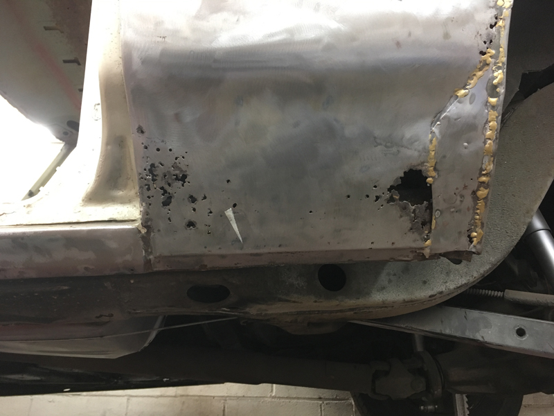
Unfortunatly a comeplete new quarter panel is not available and only 2 small repair sections for either side are reproduced. The area at the bottom infront off and behind the wheel, you can see here just how much the metal has rotted away. All of this was just covered with filler and fibreglass to hide the rust:
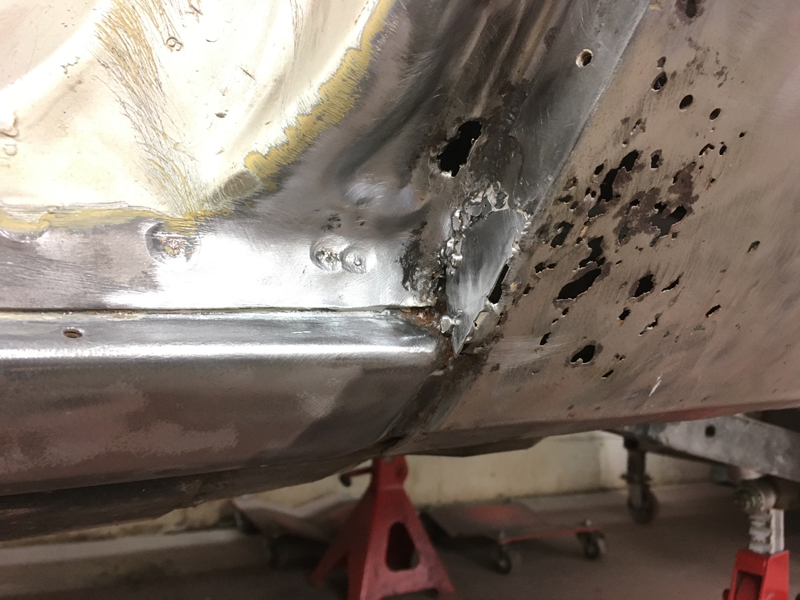
This is the repair section for infront of the wheel. It came with surface rust on it already which will need sanding off:
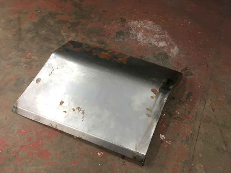
We marked out rough where to start cutting the original panel and removed a section:
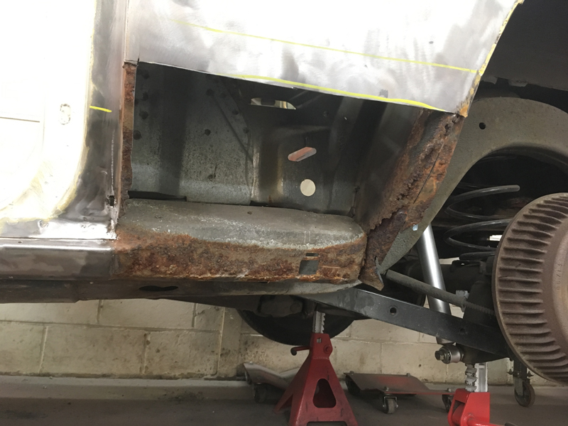
Once removed it was clear someone had been at the inner wheel arch and wheel tub areas in the past, with a plate braised over the rusted area, trapping the rust and letting it continue to spread and eat at the rest of the car over time:
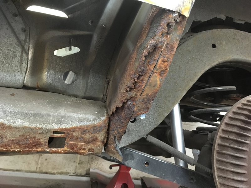
This is the same repair from inside the wheel arch. It will need cutting out and throwing away and doing properly. We say it time and time again, you can not hide or cover up rust. It must be cut out completly and new metal welded in its place or it will 100% return in time and make things worse in the long run:
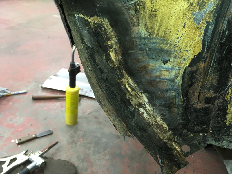
With a section of the quater panel chopped away we began trial fitting the new repair panel. Unfortunatly it was far to long and wouldn't allow the door to shut:
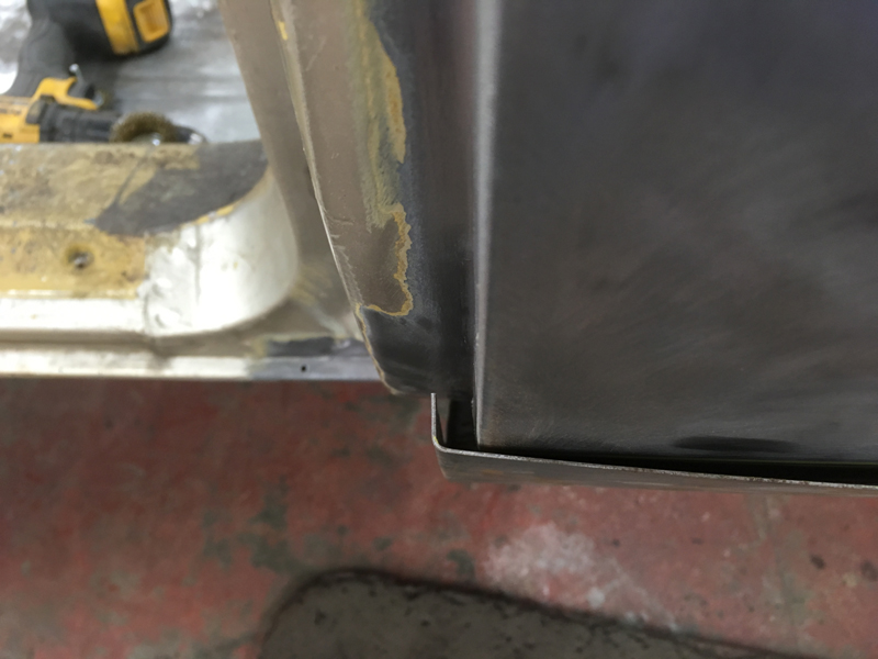
So we had no choice but to cut off the front edge of the repair panel and fabricate a new one to the correct shape and length:
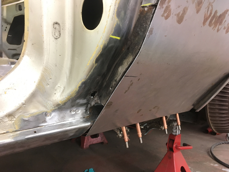
With the new front edge fabricated and complete we continued trial fitting the panel to the car:
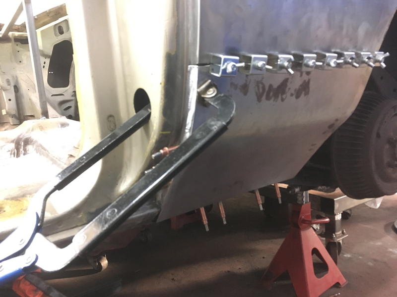
We kept cutting and trimming and adjusting the panel until we were 100% happy with its fit:
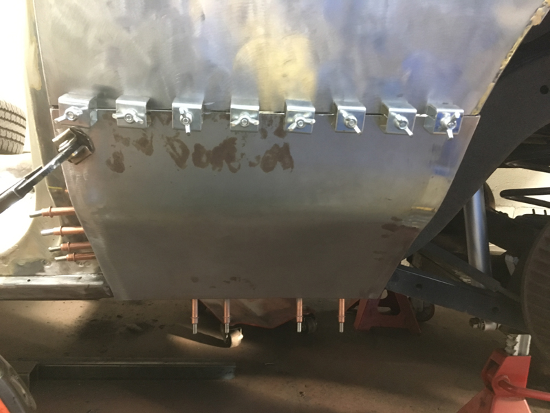
Then welded the repair panel to the rest of the quarter panel and ground the welds. Note that at this stage we are not welding the panel back to the rest of the car, only the quarter panel. This is because once the quarter panel has been repaired we need to remove the entire panel to repair rusted out areas in the structures behind it, but if we removed the panel first it would be so flimsy it would fold itself out of shape:
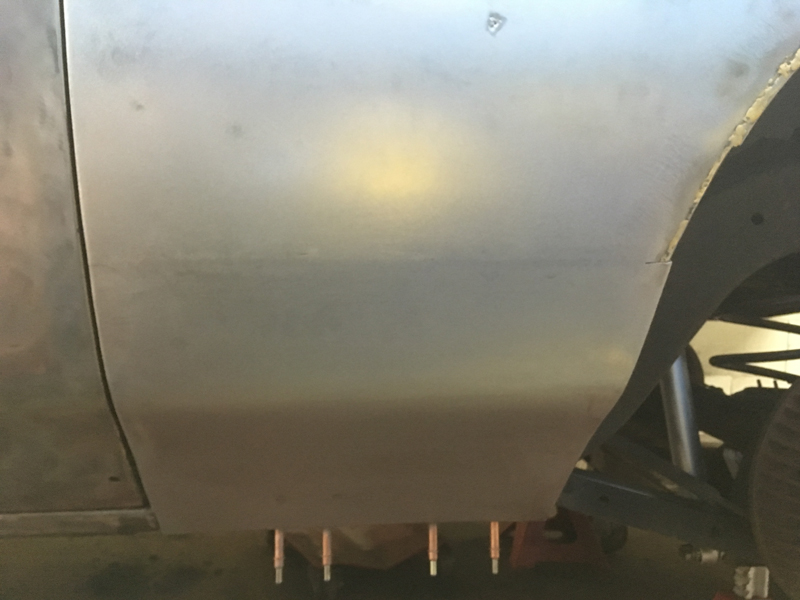
We test fitted the wheel arch moulding to the car to see how it fit the repaired area. Unfortunatly it needed some work to ge the gap nicer:
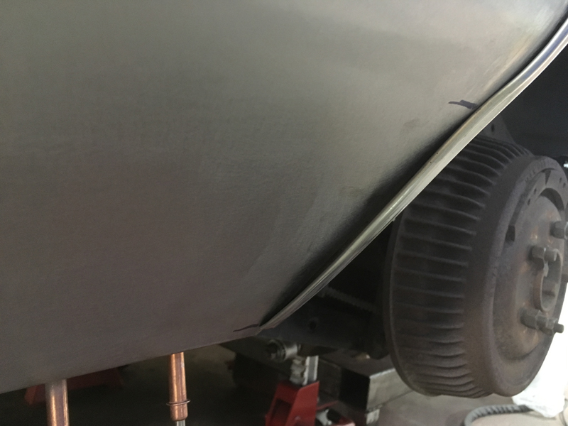
So we made a few cuts to the panel and adjusted it, then welded it shut again and ground the welds down:
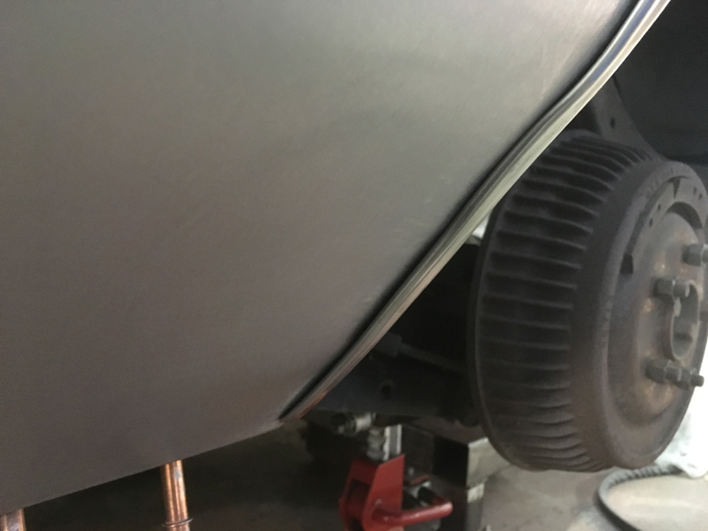
With the outer section of this area comeplete we could tackle the inner section. Its best to do smaller areas a bit at a time. Cut off too much and you loose all your references and make more work for yourself. First we cut out the previous repair and the remains of the original rust problem:
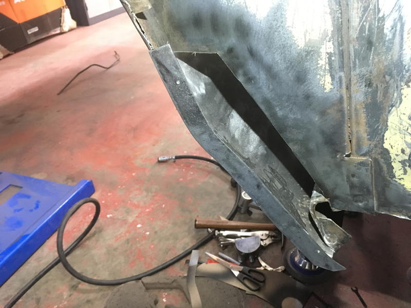
Then fabricated a new section to take its places:
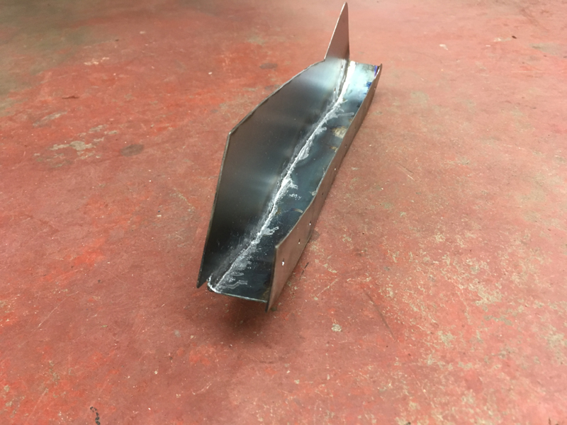
Then welded it in and ground the welds:
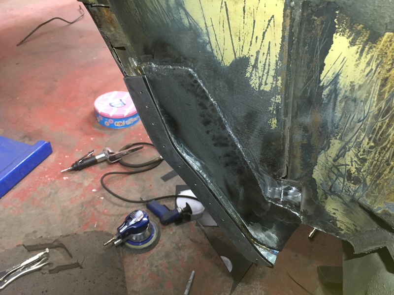
With the front section of the wheel arch and quarter panel area on this side taken care off we could turn our attention to the rear section of the panel which looked like this:
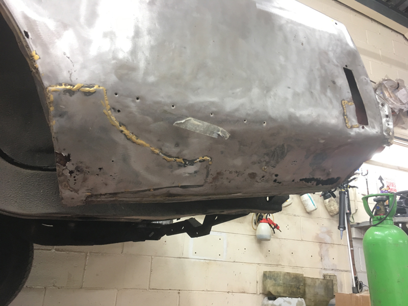
The story is the same for the rear as it was for the front, lots of bad previous repairs on top of the original rust which has come back through as it wasn't done properly the first time around:
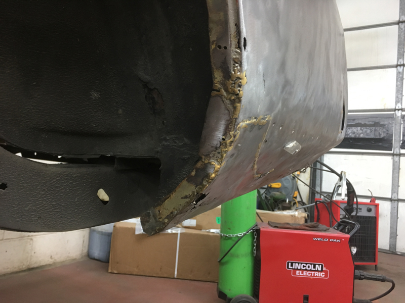
The very bottom rear edge of the panel wasn't attached at all anymore as its competly rotten away:
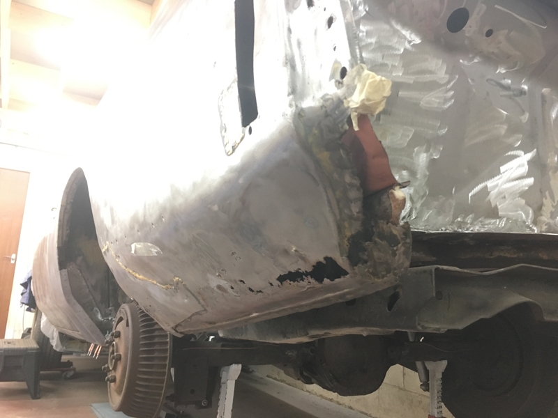
Fortunatly a with this being one of the most common rust areas for these cars a repair section is available:
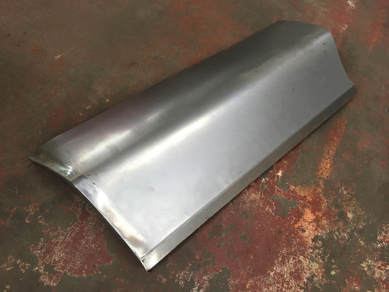
We test fitted the panel to see how it would fit:
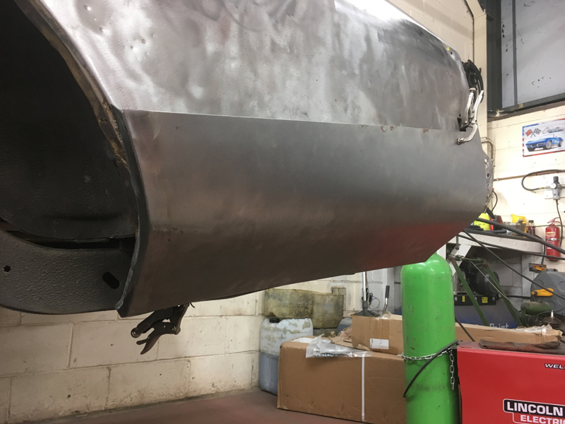
Unfortunatly the panel is competly the wrong shape at the wheel arch end and the curve in the panel is about 1.5 inches too far down the panel:
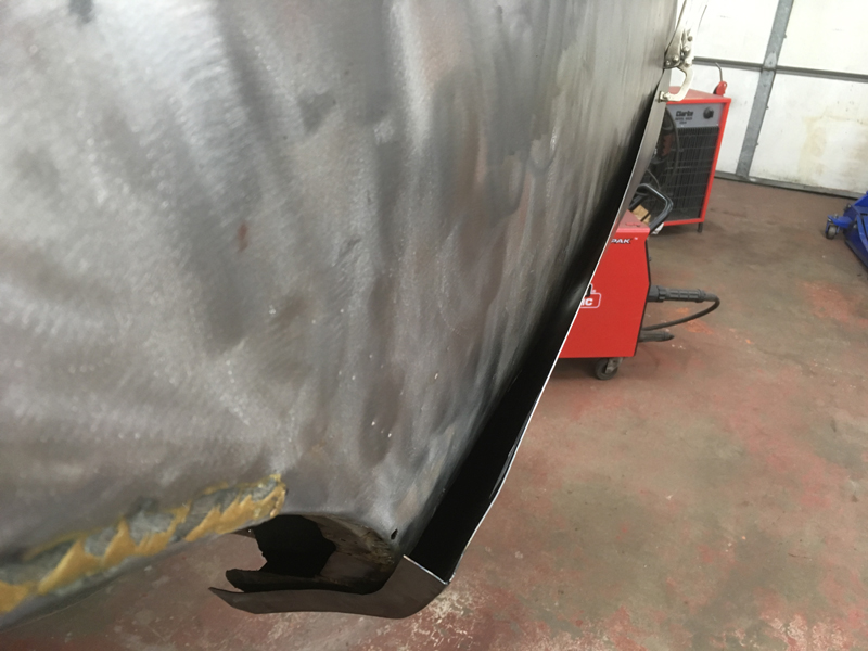
We had to cut the front wheel arch lip off from the panel, and flatten the panel back out, mark where the curve needs to be, re-curve the panel and then fabricate a new wheel arch lip and weld it back on to the panel:
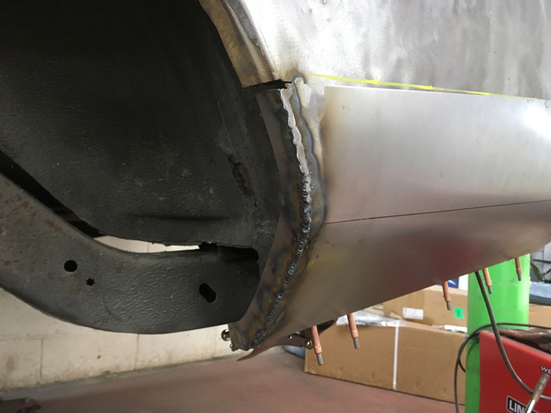
Also the rear edge of the panel was roughly 2 inches too short, so we had to fabricate a small section of steel with the same shape to it as the panel and then weld it on to the panel:
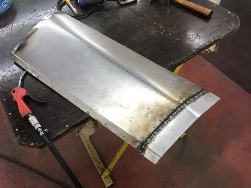
Then grind the welds on the repair panel. This is how the repair panel should have come but unfortunatly all the repair panels for these cars are hand made and can vary from panel to panel:
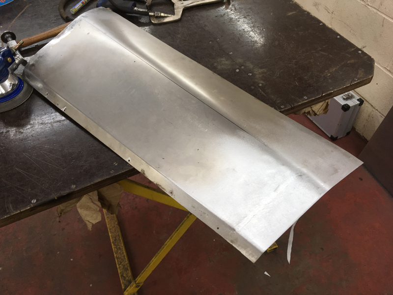
Before we could weld this panel to the car we had to address a small rusted out section of the boot floor drop off which was easier to access with the outer repair panel out the way, first we cut away the rusted edge:
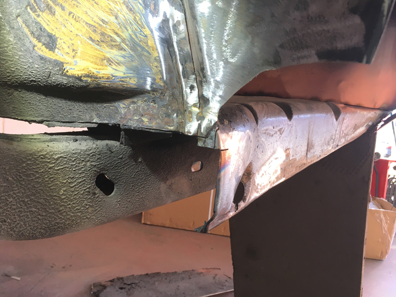
Then fabricated a repair piece and welded it into place and ground the welds:
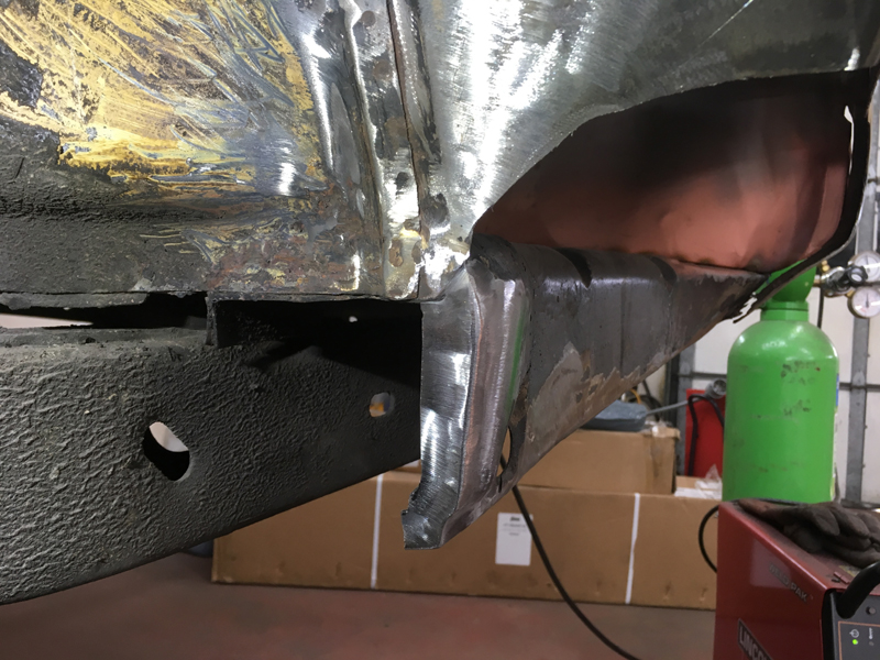
Then we carried out the final cutting and test fit of the outer panel until we were happy with the fit:
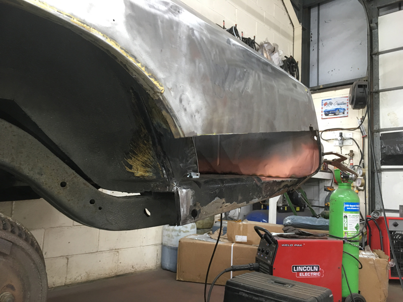
Then clamped the repair panel onto the car tightly and checked the fit one final time:
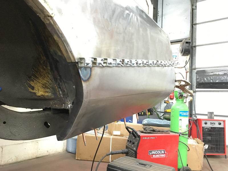
Then welded it into place:
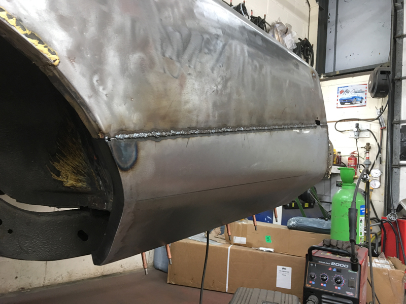
And ground the welds. We havent welded the front wheel are lip yet as further repairs to the rest of the wheel are lip are still needed but its best to tackle a job of this size when complete panels are NOT availble in sections are you will loose the shape of the panel easily:
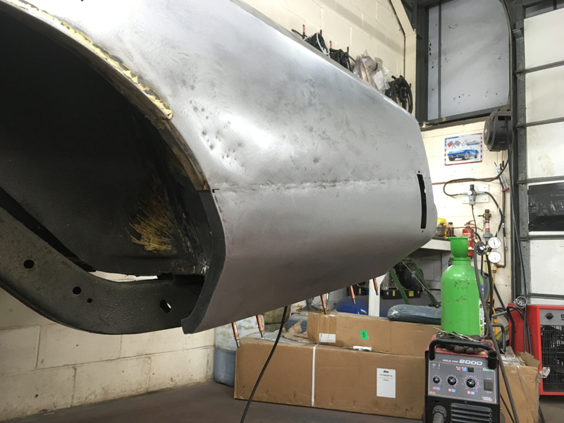
We marked out the hole for the side marker lamp to mount we. Before we cut away the original panel we made a cardboard template of this hole. With the new panel welded on we simply transferd the template back onto the metal:
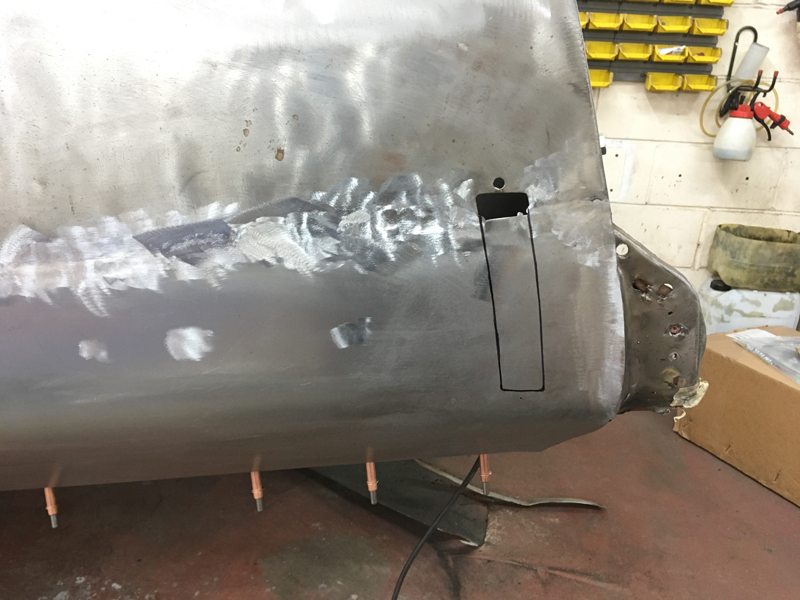
And re-cut the hole back into the metal:
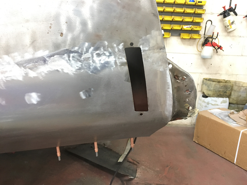
The very rear bottom edge of the panel curves in towards the car, we heated the panel and re-curved the bottom edge to make it the correct shape:
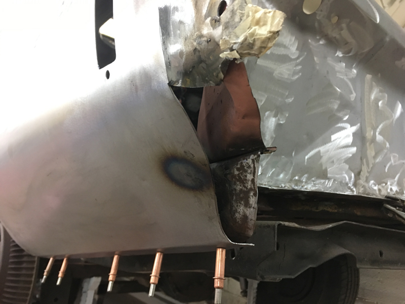
And then fabricated the remaining edge of the rear of the quarter panel for where it joins on to the rear panel of the car:
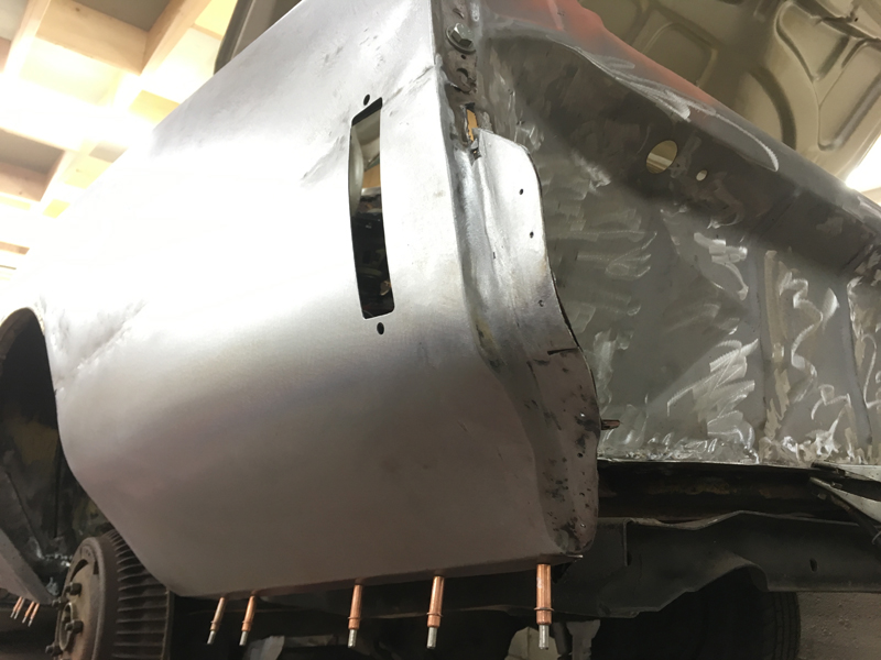
The inner wheel arch/wheel tub area on the rear of the arch was also rusted away so we had to fabricate a new piece:
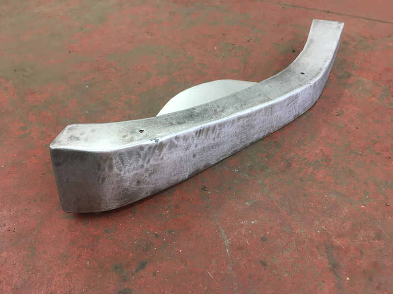
Then weld it in and grind the welds down:
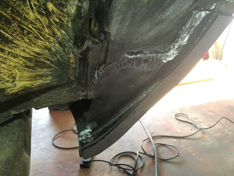
With both the front and rear ends of the quarter panel/wheel arch area finished we could tackle the remaining middle section of the arch. Someone had braised on a new lip but not joined it onto anything on the inner arch as there was nothing there to join it too. Also during the braising process they managed to get the panel too hot and warped the panel, the various holes in the panel are where they have used a slide hammer with sheet metal screws to try and pull the panel back into shape:
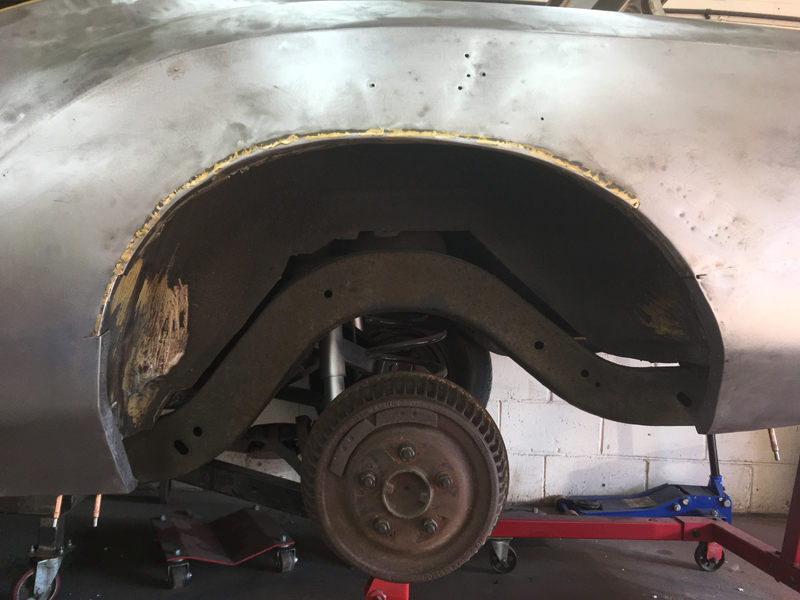
We started by fabricating a complete new outer wheel arch:
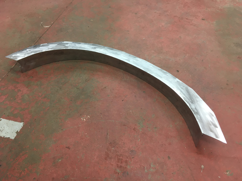
Then after alot of test fitting and cutting and more test fitting, clamped it into place and welded it on:
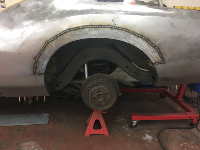
We also welded up the holes that someone had made for the sheet metal screw slide hammer, ground all the welds and then used our spot weld slide hammer to carefully pull the panel back into shape:
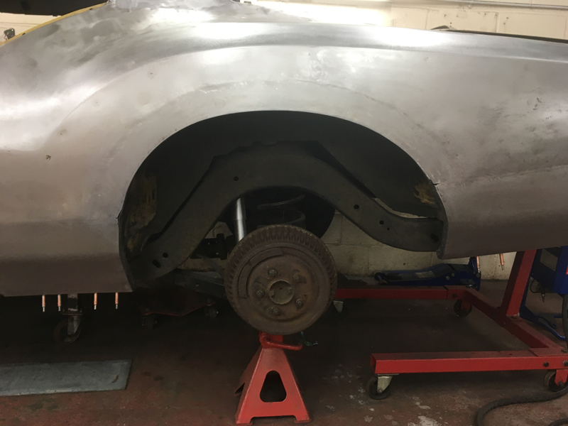
The panel still needs some more work, but once we have finished the rest of the rust repairs to the window frame area and boot lid gutter area we plan to remove the quarter panel from the car as one piece, so that we can carry out the repairs needed to areas behind the quarter panel which are in-accesable with the panel on. With the panel off we can hammer and dolly the panel and work more on the shape of the panel so that once its welded back on the car for the final time the fit and finish of the panel will be spot on:
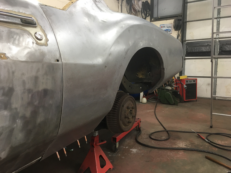
Next up we had to fabricate the inner wheel well lip area as it was complelty missing. We started by cutting a strip of metal and bending it to shape then clamping it on to the outer lip of the wheel arch to form its shape:
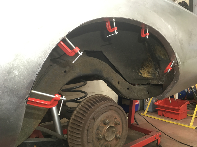
Here you can see what we are trying to achieve by having the inner part of the wheel arch take the same shape as the outer part, this is where the 2 different panels originaly are welded together:
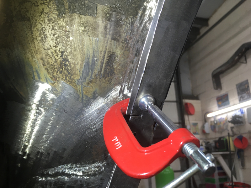
With the inner arch lip formed we could then fabricate a piece to join the lip back up to the rest of the inner wheel well:
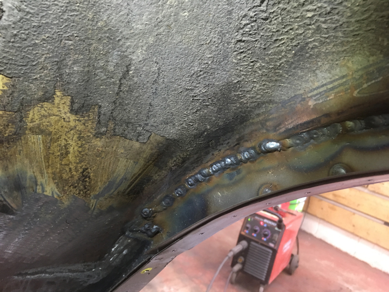
With the inner wheel well finished we had to move on to the upper joins for where the panel is welded to the car. This is a factory lead loaded seam, we needed to remove to the lead to gain access to the original weld points for the panel:
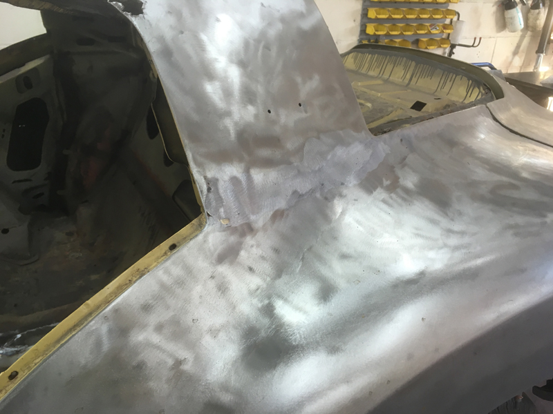
We removed the lead by heating it so that it starts to melt and then wire brushing it away and off the panel:
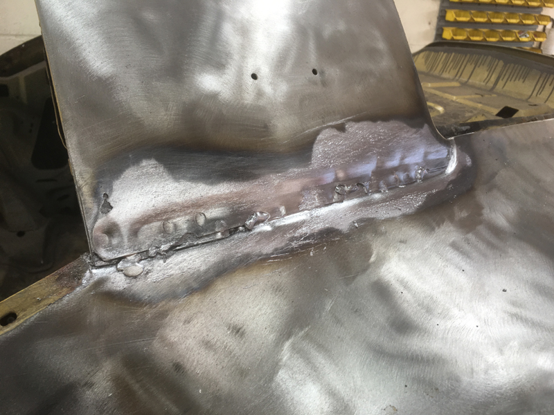
This is the boot gutter area, this mess was completly hidden with body filler:
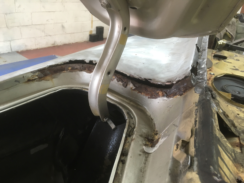
We cut out the rusted metal:
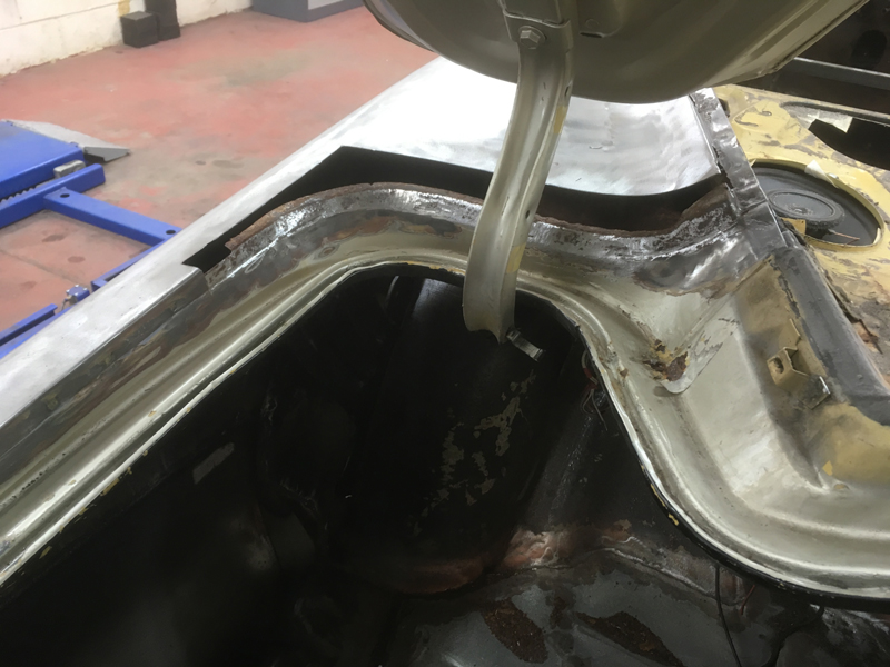
And fabricated a replacement section, welded it into place then ground the welds down:
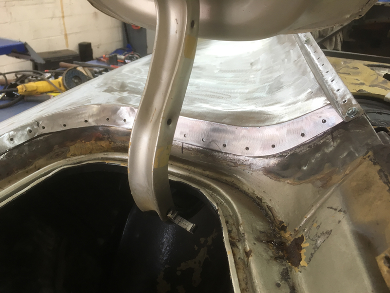
This is the rear windscreen frame area, you can see how rusted it is and why you would be getting water leaks in the car every time it rained or the car got wet:
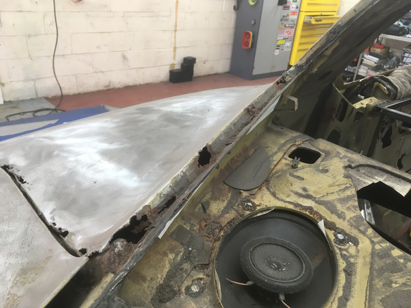
Again we cut out the rusted metal. We decided to do this in 2 halfs so that the panel didn't try to bow out of shape or move to much:
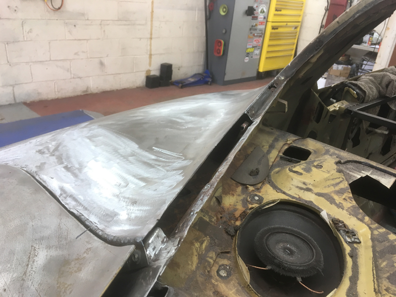
Then fabricated a replacement piece, welded it in and ground the welds then did the same with the front half of the frame area:
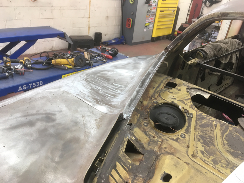
No more rust holes around this area for water to leak into and also a nice strong flat piece of metal for the rear windscreen to bond too:
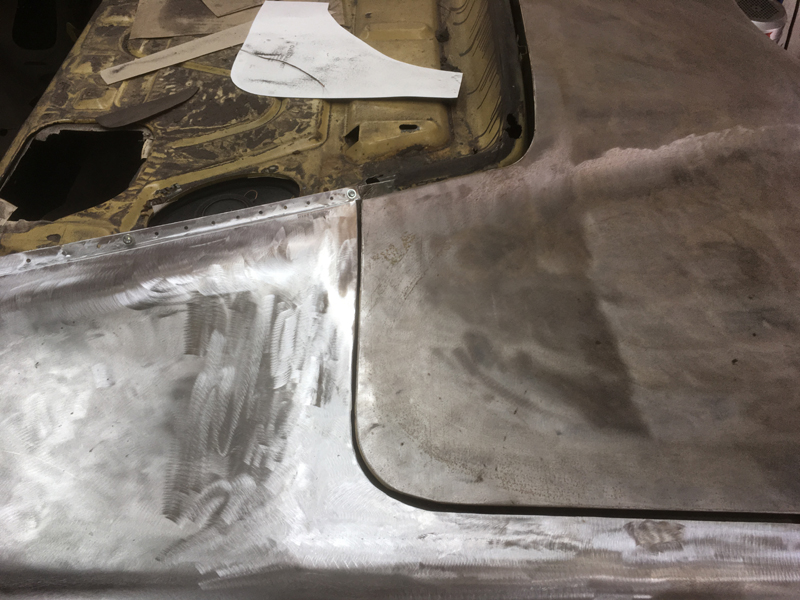
The last piece to do before we could remove the panel was the rear edge of the boot gutter channel:
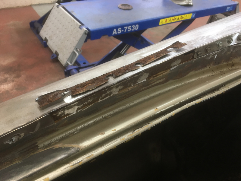
Again we did this in 2 halfs to stop the panel loosing its shape as its such a large panel. The rust was cut out, new pieces fabricated and welded in:
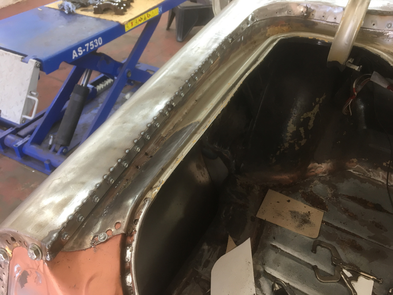
Then the welds ground down:
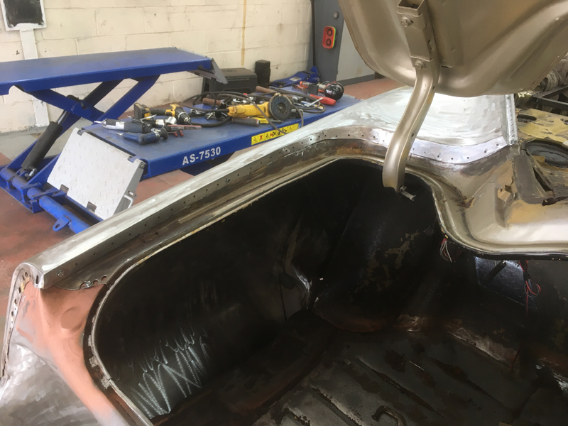
With all the edges now repaired we could remove the quarter panel from the car so that we could finish up the repairs needed to the metal behind it and work the panel some more now that we can have access to the back of it:
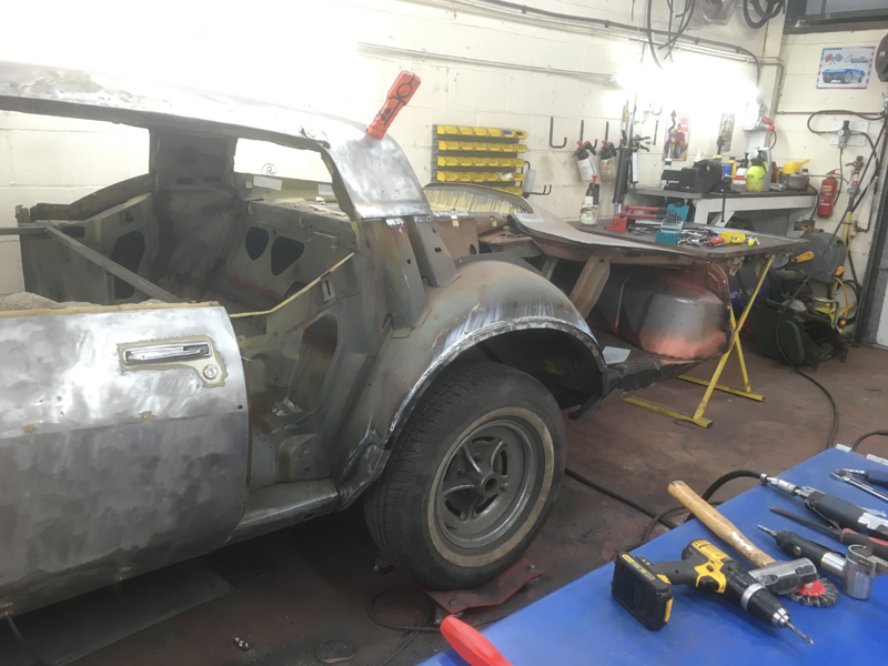
Here is the panel off from the car in 1 piece:
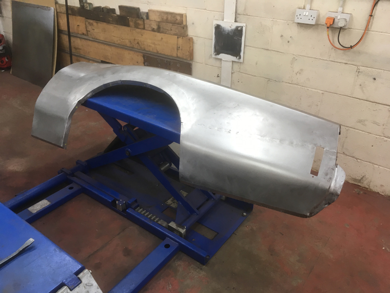
You can see from the back now just how much has actually been replaced. You can also see the heavily rusted area at the top which we would never have been able to clean up with the panel on the car due to the strutural pieces of metal that make up the boot lid hinge mounting points:
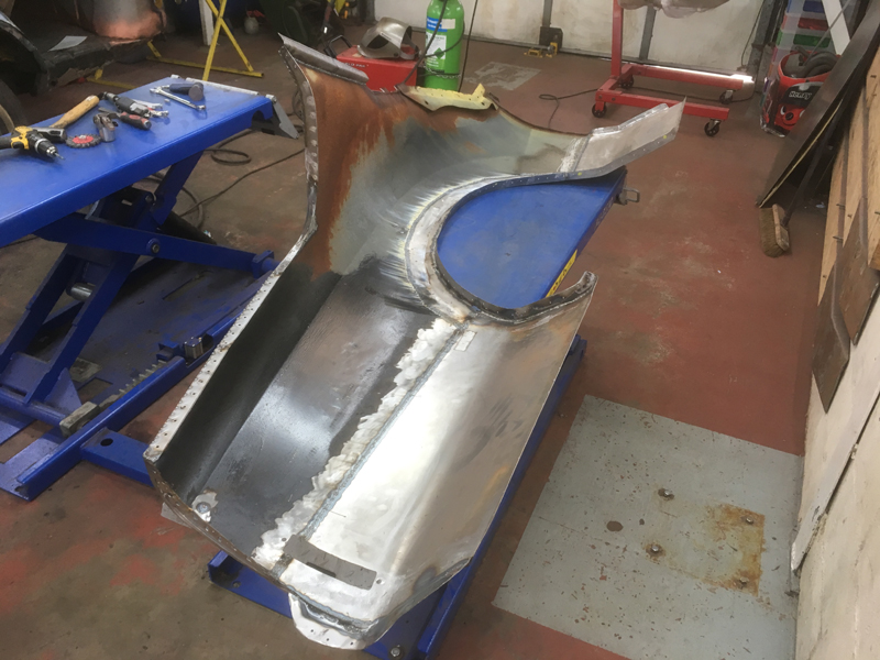
We ground the welds on the rear of the panel so that we could work the panel some more and also bare metaled the inside of the panel and took the rusted metal back down to clean metal. Doing this we found some rust pin holes which needed welding up. We plan to paint the entire inside of the panel in rust prevention paint before it gets welded back on to ensure the rust wont come back:
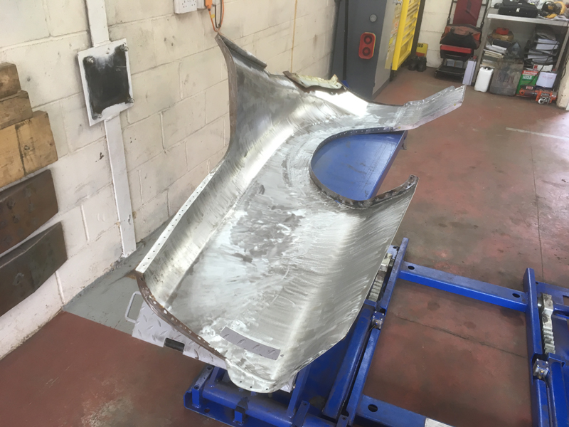
Next we cut away the rest of the rusted metal on the panel, then screwed the panel back onto the car so we could fabricate the remaining pieces for it, starting with the rest of the door shut edge:
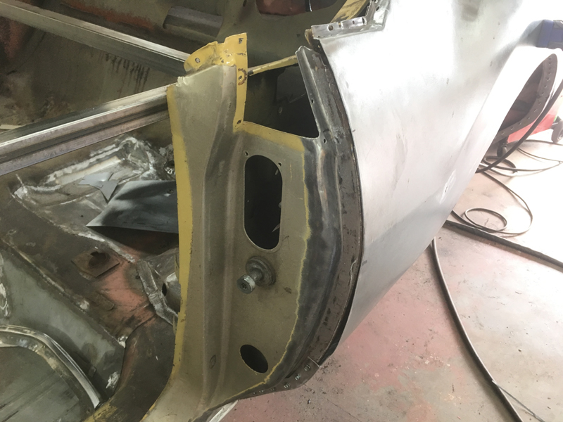
We fabricated a new edge piece and welded it into place then ground the welds:
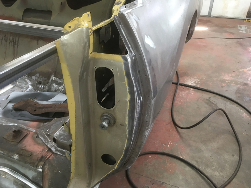
Then it was onto the recessed roof edge piece where the roof panel overlaps onto the quarter panel:
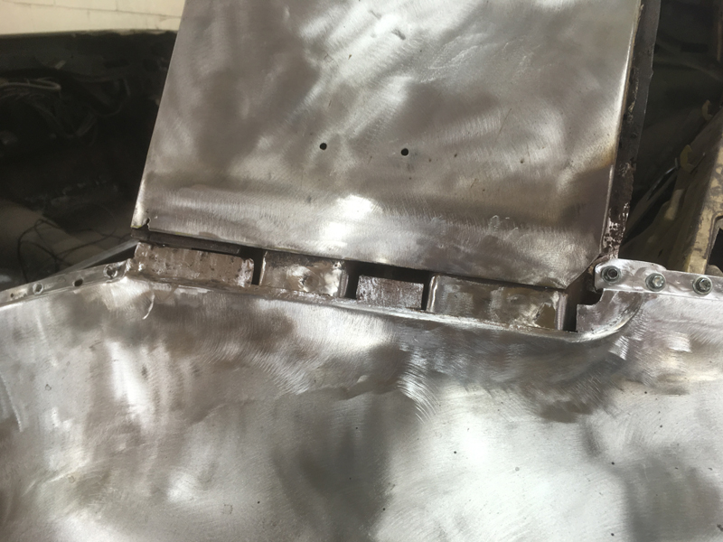
The new section was fabricated and welded into place and welds ground:
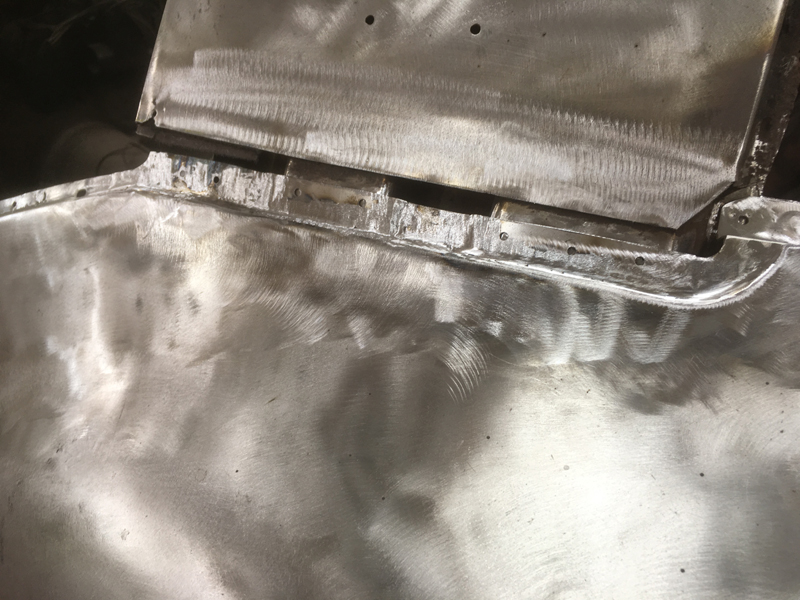
This section on the rear panel and the quarter where both rusted away leaving a hole in both panels that needed to be filled:
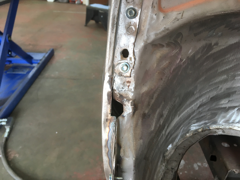
We removed the quarter panel to access the rear panel:
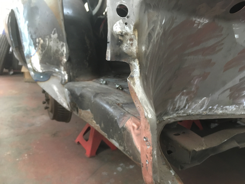
Then welded a small section into place and ground the welds:
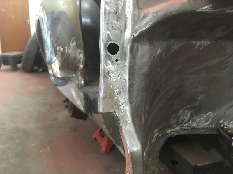
Then did the same for the quarter panel:
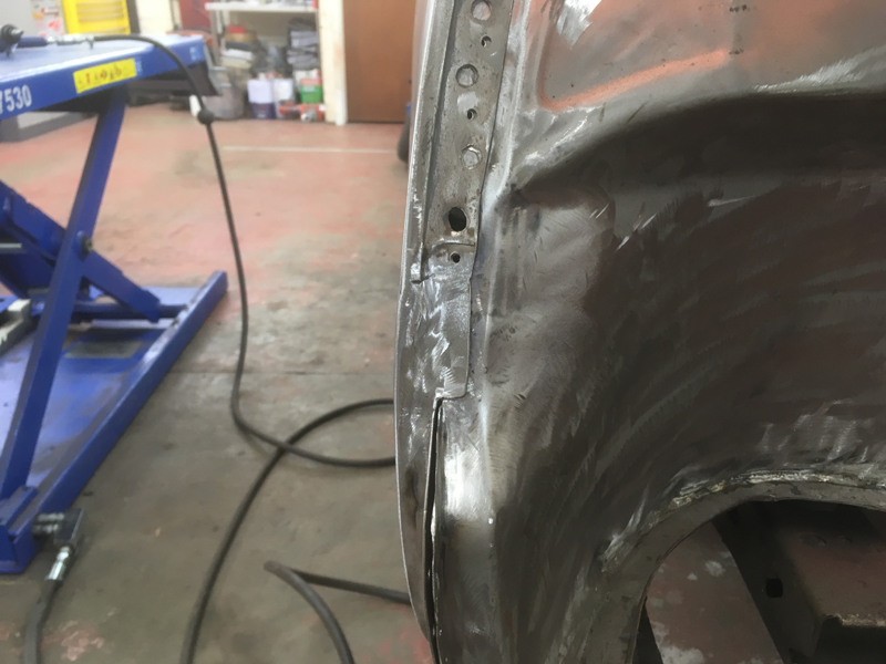
With the repairs to the rest of the quarter now complete we only had the strengthening piece to address where the rear wind down window goes:
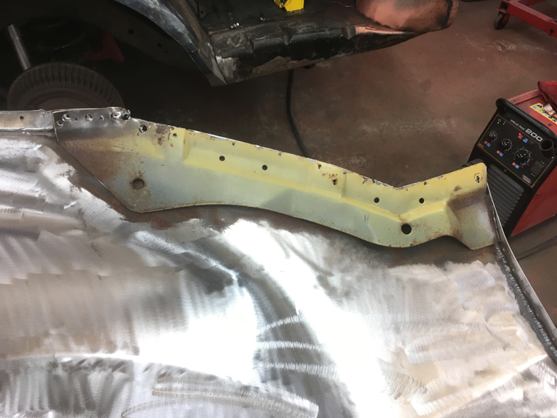
We drilled the spot welds and removed the piece to find the remaining rusted steel and pin holes behind it:
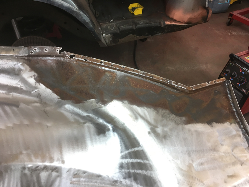
With the rust holes welded up, we cleaned up the steel back to clean metal:
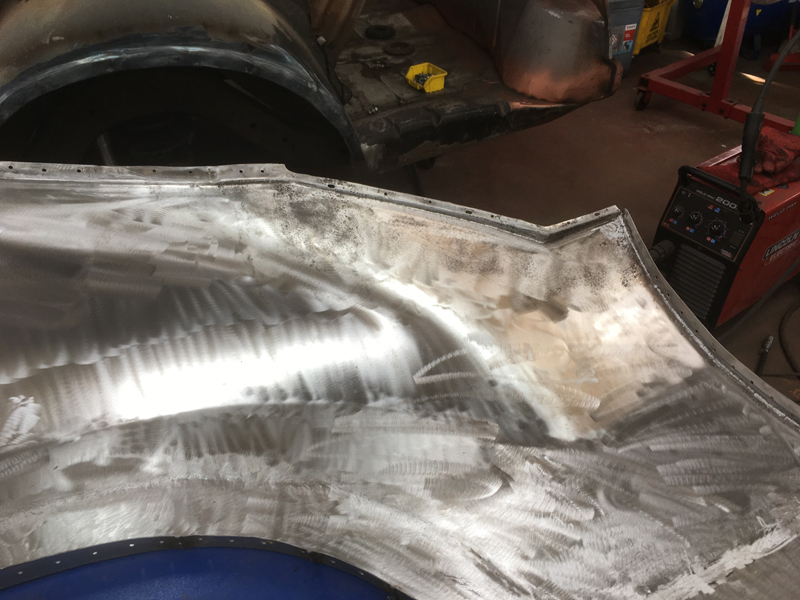
Then turned our attention to the strengthening piece itself:
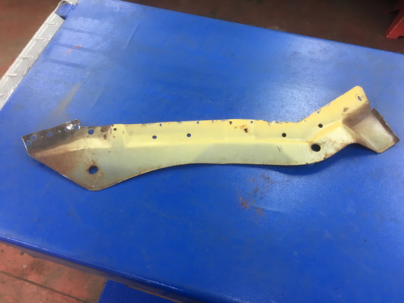
We took it back to bare metal on both sides and welded up the rust holes in it:
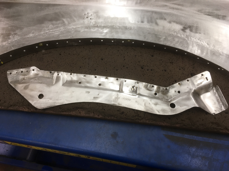
The back side of it was far worse than the front:
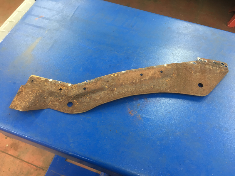
But still savable:
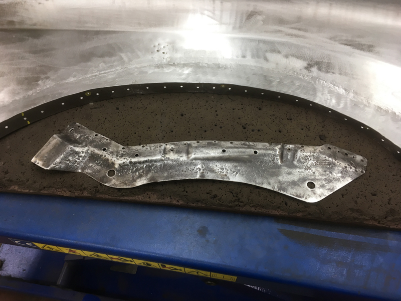
Next we did some final hammer and dolly work on the quarter panel and keyed up the inside of the panel so and gave it a good clean and de-grease:
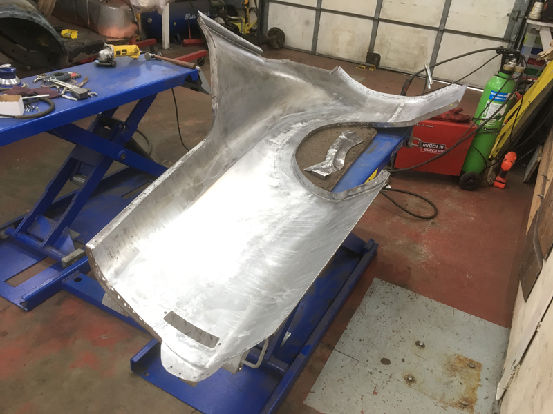
Then we applied a rust preventative coating which does 2 jobs, it neutralises any metal that had surface rust which has been cleaned back to clean metal so stop it rusting again and it also forms a thick skin on the metal to stop the good new metal from going rusty:
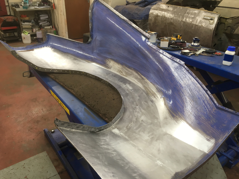
It takes 24 hours to cure fully but once dry its a very tough skin that will protect the metal:
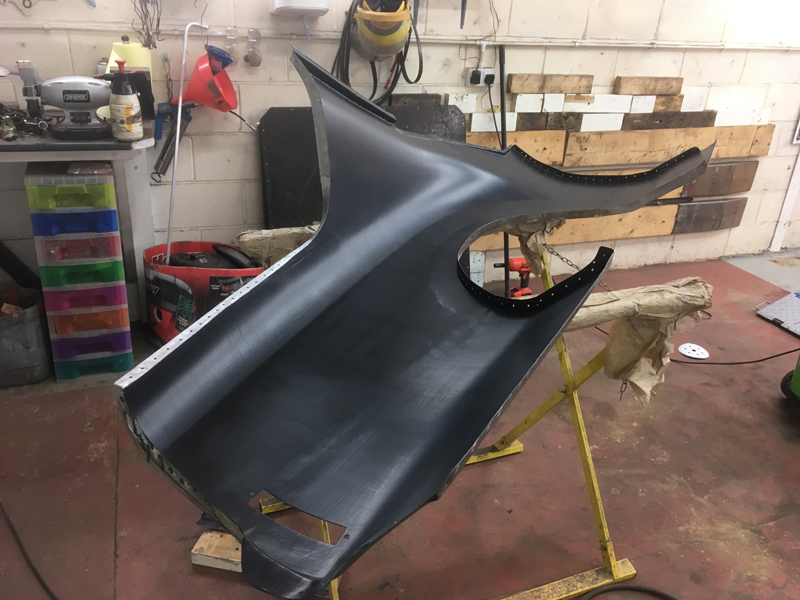
We did the same treatment to the strengthening piece on both sides:
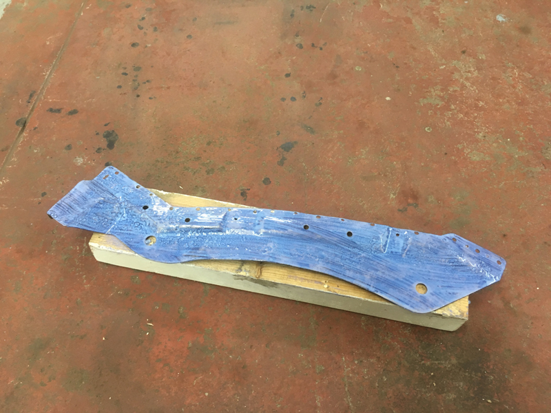
Then once dry we welded it back onto the quarter panel:
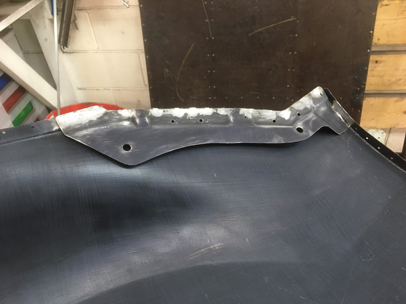
With the panel finished we then turned our attention to the body shell and the metal behind it:
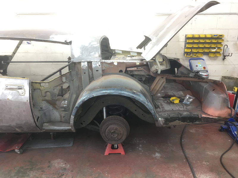
There was a rust hole in the door shut edge:
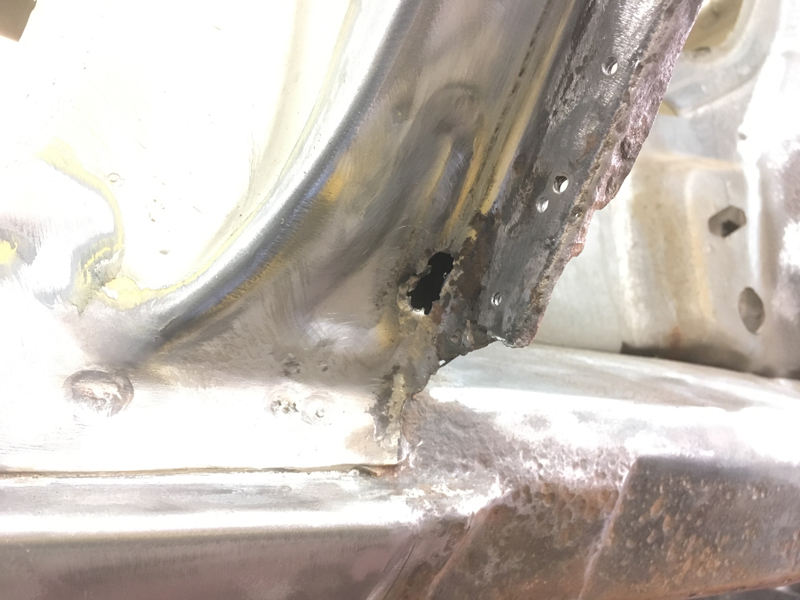
Which we welded up and ground down:
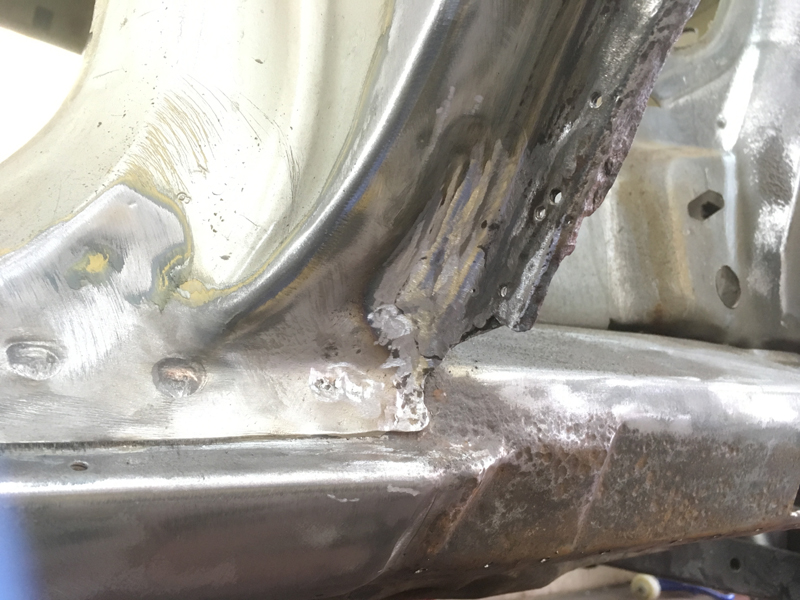
There were some holes along the inner rear windscreen frame metal work area:
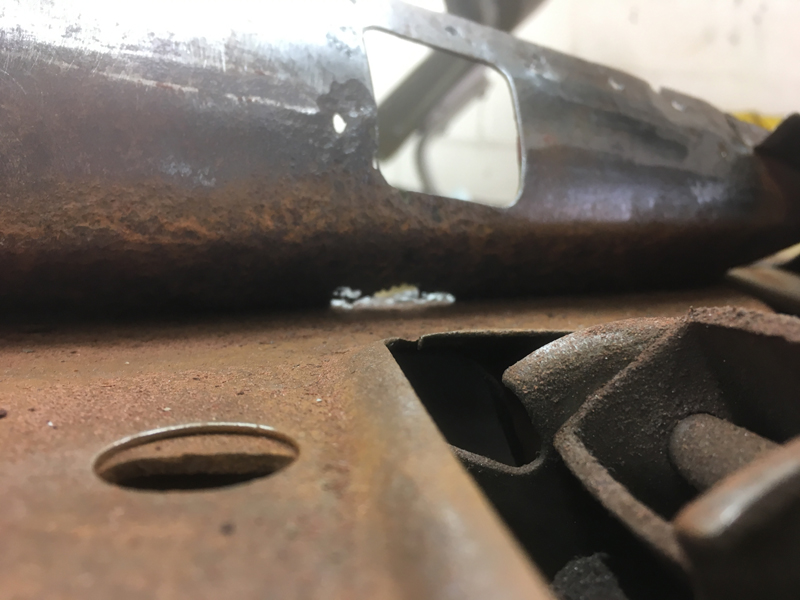
Which again we welded and ground down:
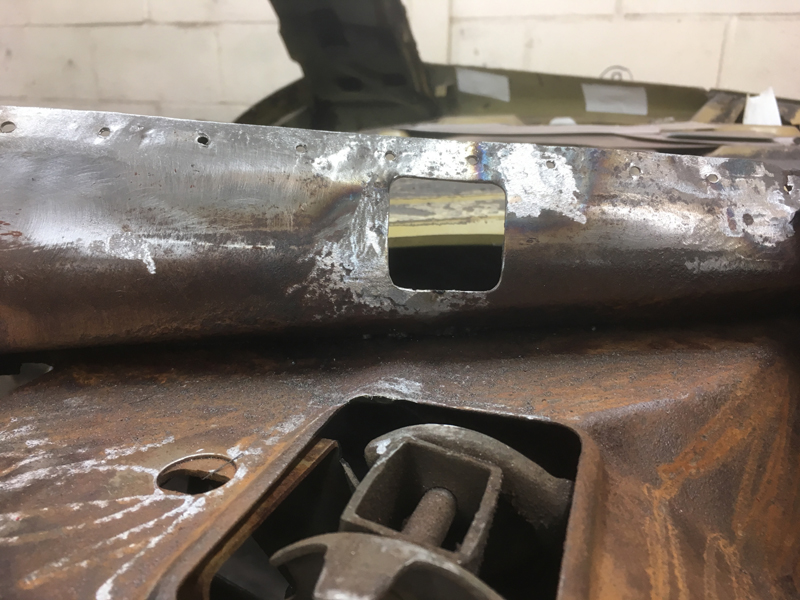
There was this rust hole in the rear package tray area:
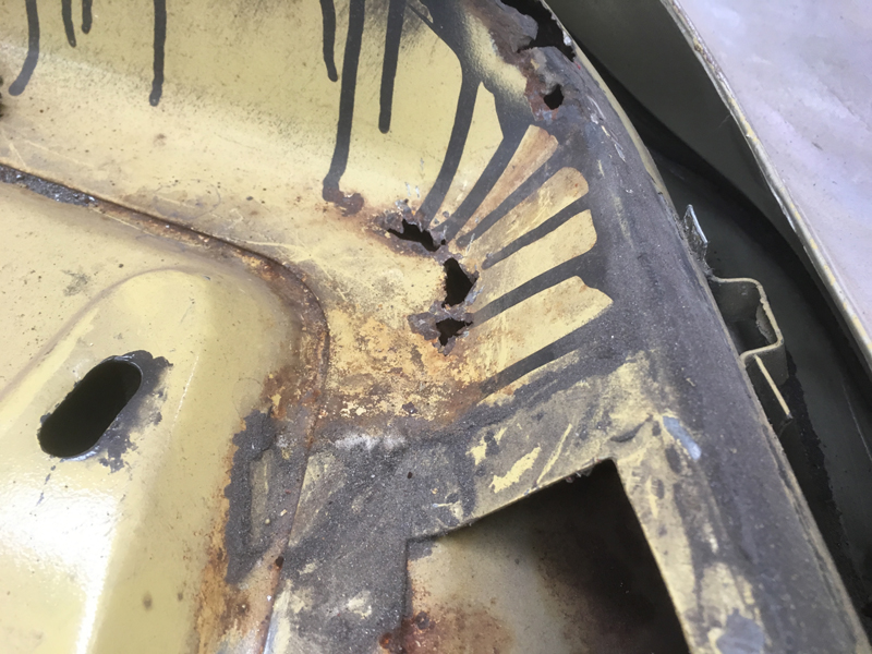
Welded up and ground back:
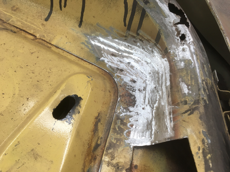
There was this large hole in the rear windscreen frame rear edge:
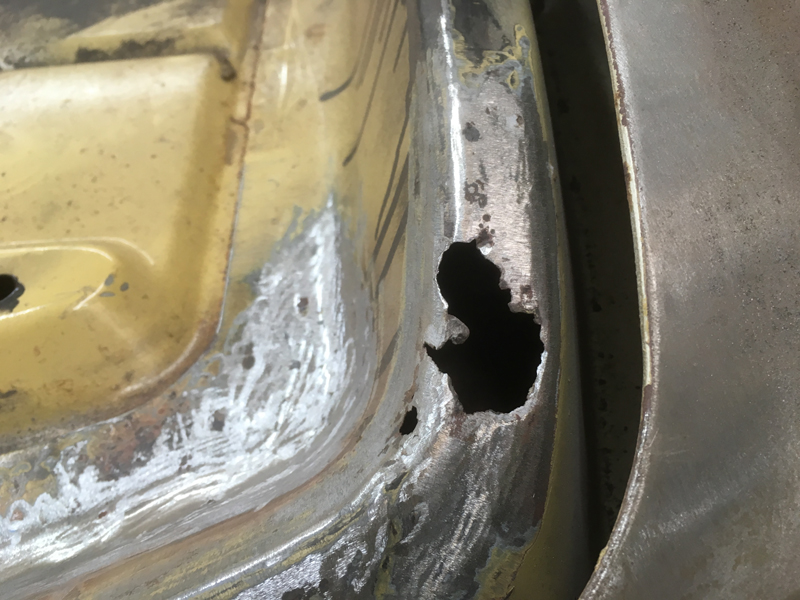
Which we cut out:
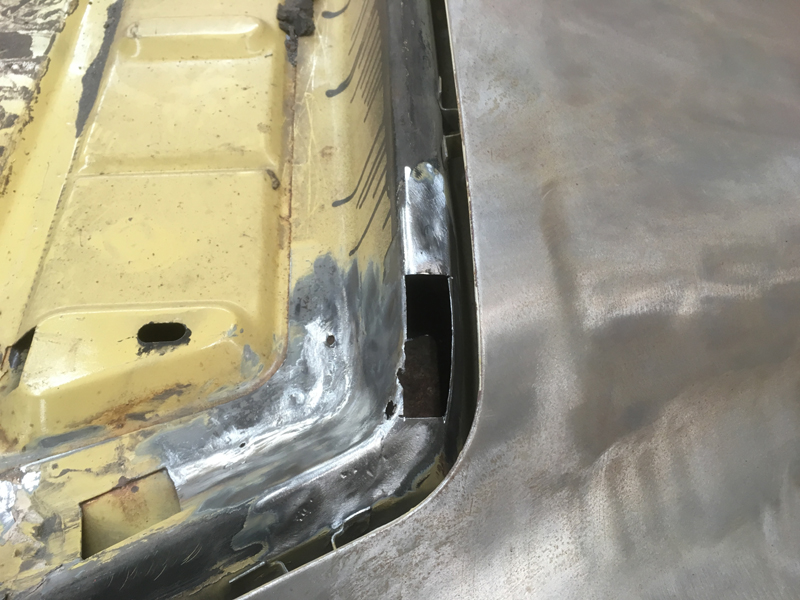
Fabricated a top piece and welded it in then cut out the front edge part of it:
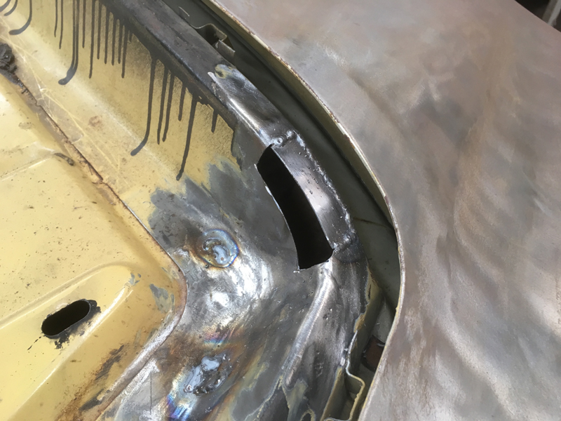
Then made a front piece and welded it in then ground all the welds flat:
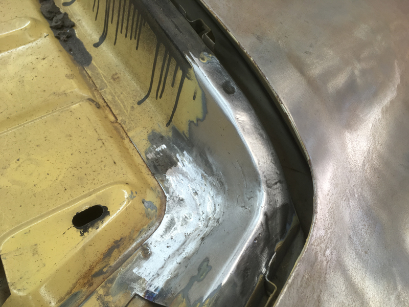
The final rust area was in the boot gutter area:
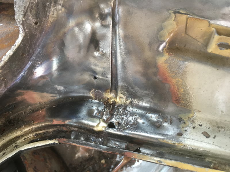
Which as you can see up close was very rusty:
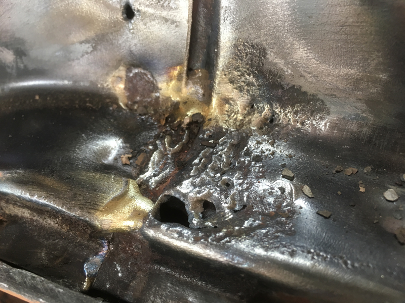
So we cut the rusted steel out and cleaned up the metal behind it:
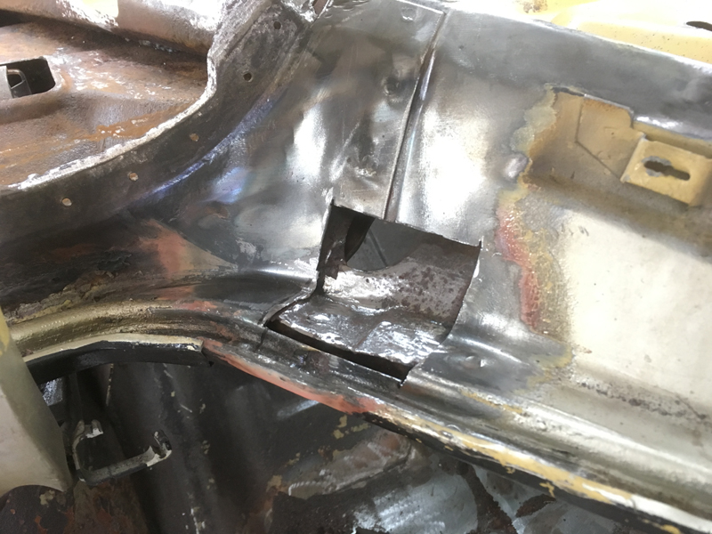
Then welded in a new piece:
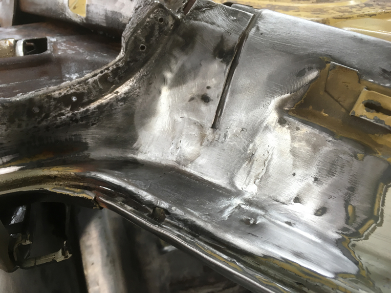
With all the rust taken care of, we took the rest of the metal back to bare clean steel:
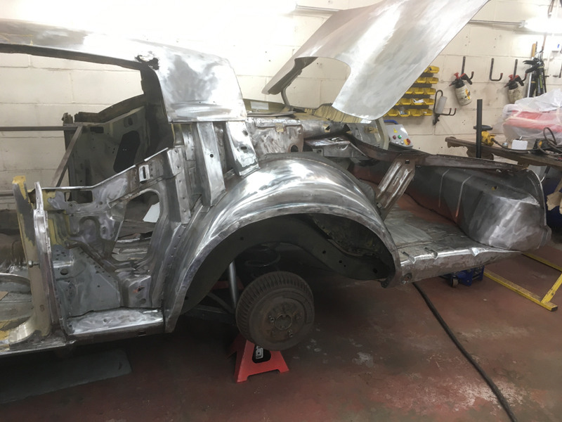
Then using a blow lamp and scrapper, removed all the old hard and flaking underseal out from the wheel arch area:
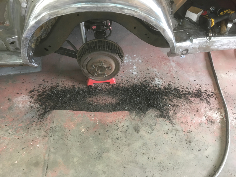
We did this now so that we didn't have to do it once all the inner sheet metal was given a fresh coat of paint as the heat from the blow lamp would have lifted the paint on the inside away from the metal:
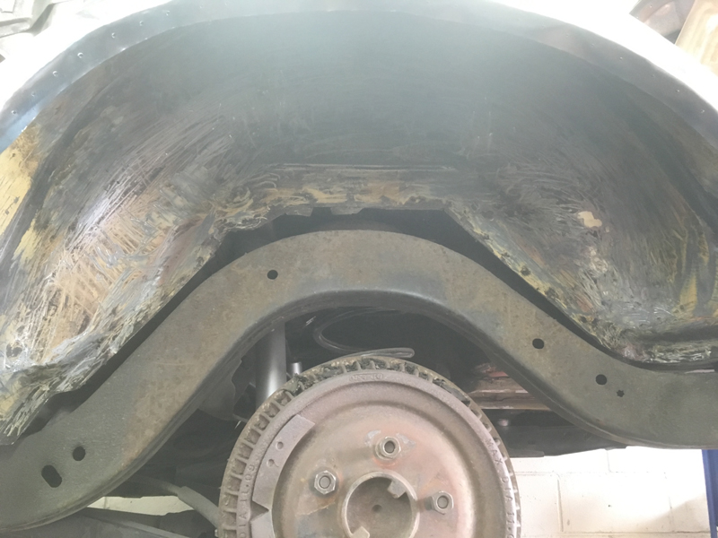
Next we keyed up and de-greased all the inner sheet metal then coated it in the rust preventative coating:
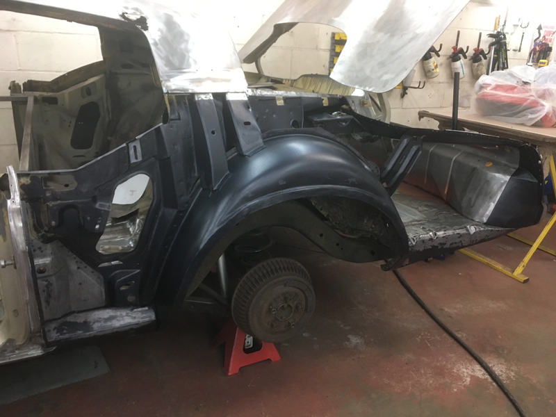
Once it had fully cured we gave the coating a light key up and clean then painted it in an anti-rust primer:
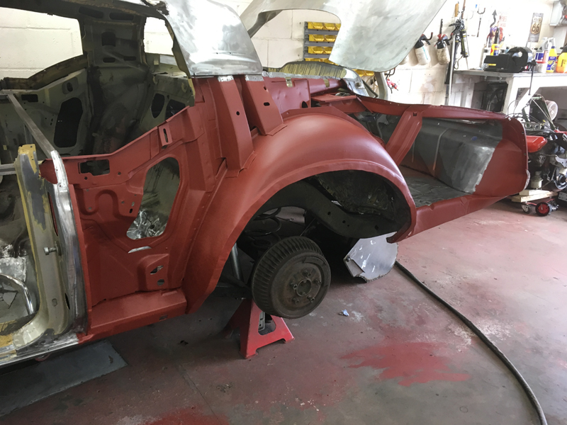
And did the same thing for the inside of the quarter panel:
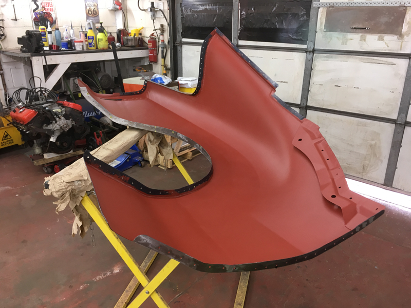
With the primer dry we sanded the edges of the panel back to bare metal in preparation for welding:
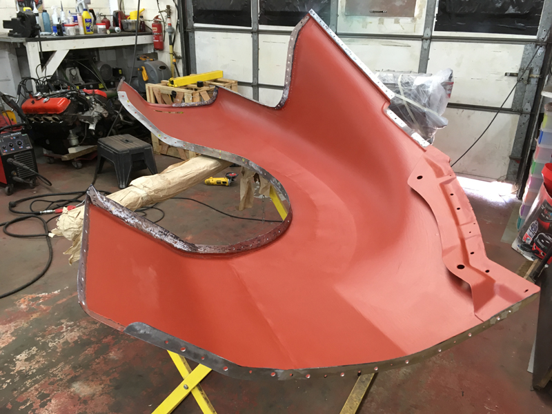
Then painted the edges of the panel in weld through primer:
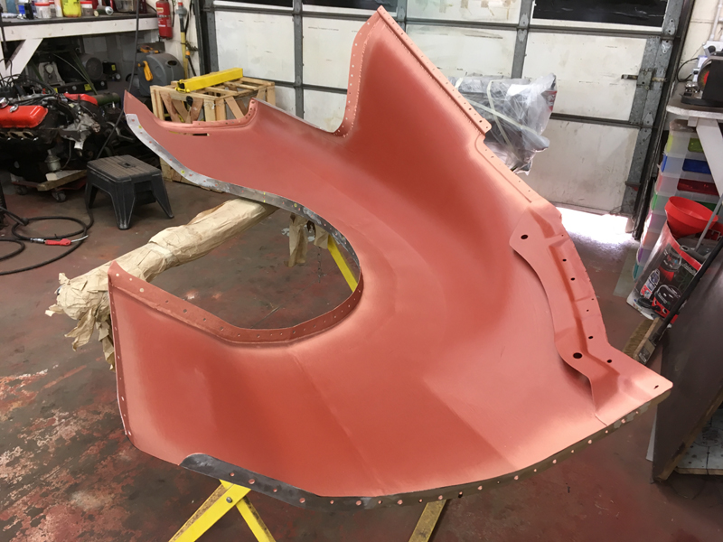
And then did the same thing to the body of the car:
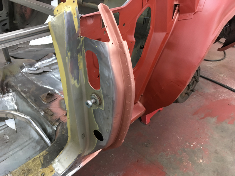
Next we put the panel back onto the car and checked the alignment of the panel:
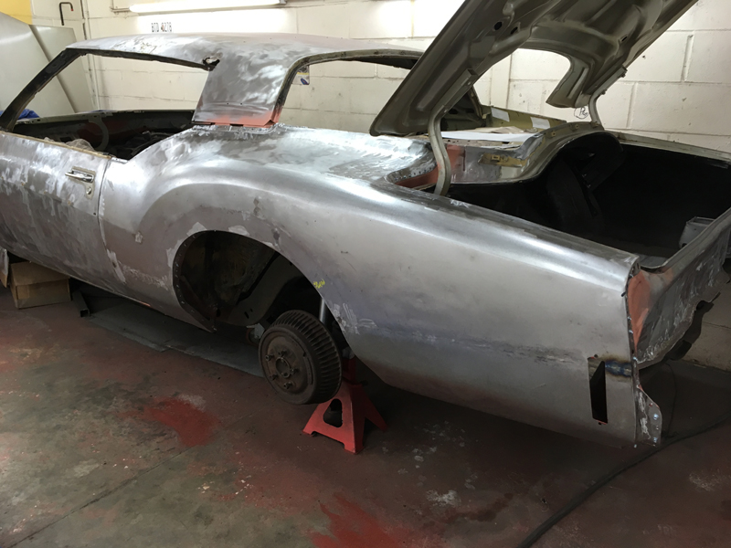
Once happy with the fit of the panel, we screwed it down into place in every other hole:
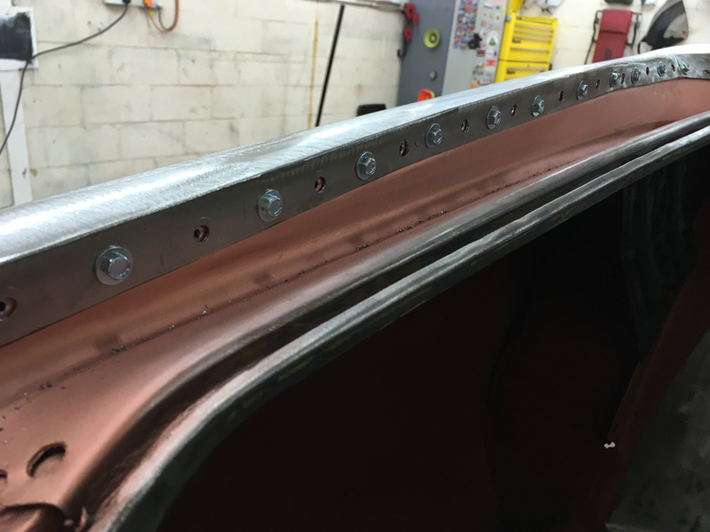
Then plug welded the panel into place through the holes with no screws in, then removed the screws and welded those holes too:
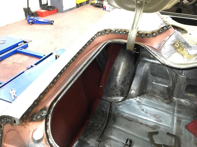
Next we ground the welds down:
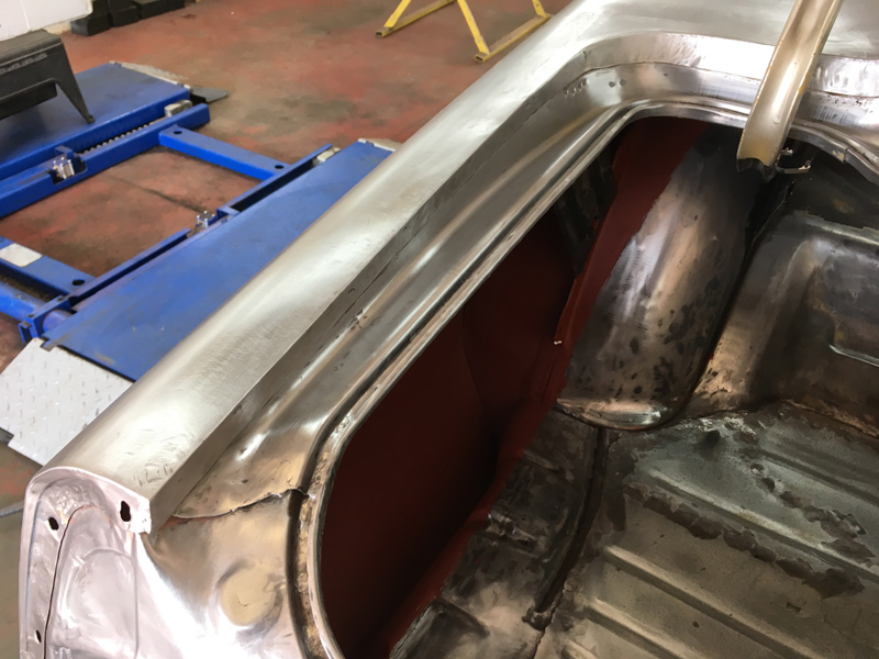
With the welding to the driver's quarter panel and rear panel complete we decided it best to put some primer over this bare steel to stop the moisture in the air attacking it so we prepped the metal for paint:
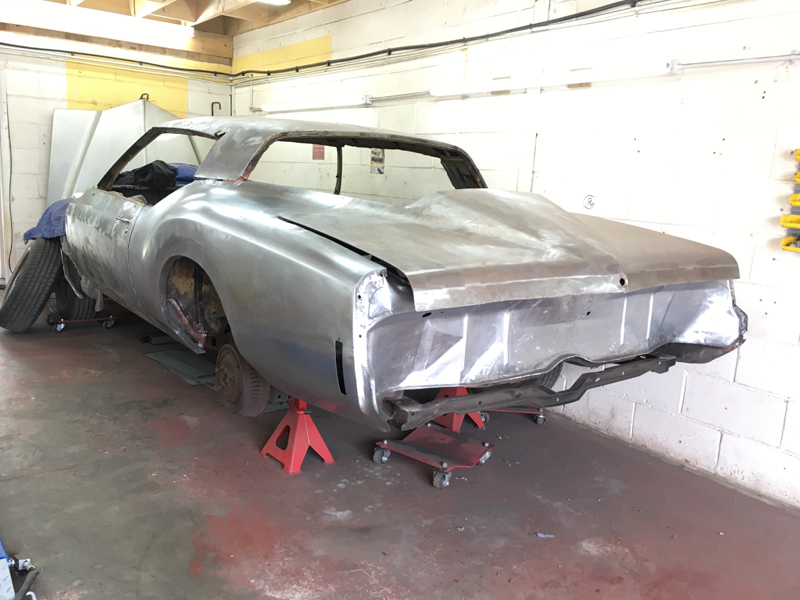
At this stage we are not doing the filler work to the body, we will have all that done in one stage once the welding to the body is complete. We masked up the rest of the car as we didn't want paint over it all yet since the rest still needs work:
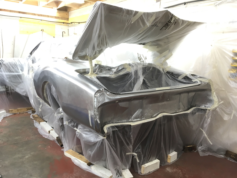
Then sprayed it with etch primer:
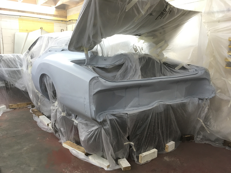
Followed by an anti-rust primer which will protect the steel from rusting. Once the welding is complete the car will go off to the paintshop to have the rest of the body and paintwork finished: